Dovetail flip bucket and fitting slope aeration method and structure

A technology of swallowing ridges and slopes, which is applied in water conservancy projects, sea area projects, coastline protection, etc., and can solve problems such as poor aeration effect

Active Publication Date: 2016-01-06
NANJING HYDRAULIC RES INST
View PDF4 Cites 6 Cited by
  • Summary
  • Abstract
  • Description
  • Claims
  • Application Information

AI Technical Summary

Problems solved by technology

[0005] The invention proposes an aeration method and structure of "Yanwei ridge + sticking slope", which mainly solves the proble

Method used


Image

  • Dovetail flip bucket and fitting slope aeration method and structure
  • Dovetail flip bucket and fitting slope aeration method and structure
  • Dovetail flip bucket and fitting slope aeration method and structure

Examples


Embodiment 1

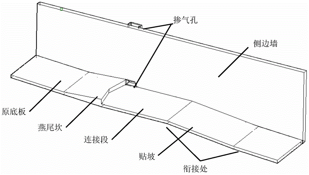
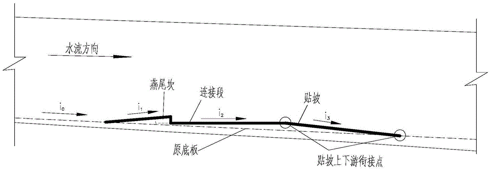
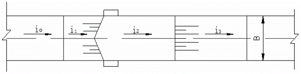
[0021] Such as Figure 1-3 As shown, the aeration structure of this embodiment consists of a dovetail groove at the end of the upstream end ( figure 2 Middle Yanwei ridge section, slope i 1 ), and the slope at the downstream end that is larger than the slope of the bottom plate of the discharge channel ( figure 2 Middle paste slope section, slope i 3 ) and the connecting section connecting the ridge and the slope ( figure 2 middle link, slope i 2 )composition. The slope and the connecting section and the downstream original floor are connected by points (point connection on the section view and straight line connection on the plan view). The connecting section is a flat slope (i 2 =0).

Embodiment 2

[0023] Such as Figure 4 As shown, the aeration structure of this embodiment is similar to that of Embodiment 1, the difference is that the slope and the upstream connection section are connected by a convex arc curve, and the slope and the downstream bottom plate are connected by a concave arc curve (the arc curve is shown in the cross-sectional view Connection, surface connection in plan view). The connection form can also be a straight line in the section (a straight line connection in a section view, and a plane connection in a plan view) or other curved connections.

Embodiment 3

[0025] Such as Figure 5-7As shown, the aeration structure of this embodiment is similar to that of Embodiment 1, the difference is that the slope of the bottom plate after the slope is pasted is smaller than the slope of the upstream bottom plate (i 4 ﹤i 0 ), the slope and the upstream connection section are connected by a convex arc curve, the slope and the downstream floor are connected by a concave arc curve, and the slope of the connection section is a positive slope (i 2 >0).


PUM


Abstract

The invention provides a dovetail flip bucket and fitting slope aeration method and structure. The problems that water accumulates in an aeration cavity of a small base slope and a low-Fr-value drainage flow channel and the aeration effect is poor are mainly solved. The aeration structure is mainly composed of a dovetail flip bucket, a downstream fitting slope and a connecting segment. The tail end of a conventional two-dimensional continuous linear flip bucket is provided with a V-shaped notch (the notch is shaped like a dovetail, so the V-shaped notch is called as the dovetail flip bucket), and adjustment of the nappe toss angle of the top of the flip bucket and the napple drop point distribution behind the flip bucket is beneficial for jet impact angle unification; the sharp fitting slope is arranged at the nappe drop point position of the small base slope, so that the jet impact angle is within a critical value for generating backflow water, and backflow water accumulation at the nappe drop point position of a base plate is eliminated; and the upstream end of the fitting slope is connected with the upstream flip bucket through the connecting segment, and generally, a flat slope or a right slope is adopted. The dovetail flip bucket, the fitting slope and the connecting segment form a complete system through different connecting manners. The aeration structure is simple, resistant to cavitation and erosion and high in universality, and the aeration cavity is large, stable and free of water accumulation.

Description

technical field [0001] The invention belongs to the technical field of water conservancy and hydropower engineering, and relates to an aeration-type setting method for a discharge channel, in particular to solve the problem of aeration in a discharge channel with a large single width, a small bottom slope, and a low Fr number. Background technique [0002] Tunnel flood discharge is widely used in water conservancy and hydropower projects. According to the layout form, it can be divided into dragon head type, dragon tail type and one slope to the bottom. When the height difference between the entrance and exit is large, the dragon head and dragon tail are often used; when the height difference is small, the longitudinal drop is limited and the slope of the cave body is relatively gentle. Regardless of the type of layout, since flood discharge tunnels generally have a single width and a large flow rate and high flow rate, cavitation and cavitation are prone to occur, so it is ...

Claims


Application Information

Patent Timeline
IPC IPC(8): E02B8/06
Inventor 吴时强王芳芳王威吴修锋周杰沙海飞薛万云戴江玉曹昊陈惠玲
Owner NANJING HYDRAULIC RES INST
Why Eureka
Try Eureka