Heat exchanger and fin thereof

A heat exchanger and fin technology, applied in the field of heat exchange equipment components, can solve the problems of large stretching deformation of fins, inability to discharge, easy to accumulate water, etc., to reduce the difficulty of bending, smooth air circulation, and high heat exchange. performance effect

Inactive Publication Date: 2010-06-16
SANHUA HLDG GRP +1
View PDF0 Cites 15 Cited by
  • Summary
  • Abstract
  • Description
  • Claims
  • Application Information

AI Technical Summary

Problems solved by technology

[0006] However, the fin structure of the existing heat exchanger has certain limitations. Since the fins are corrugated between the flat tubes to form a number of stable triangular support structures, when bending, the inner side of the fins at the bending position will rise. The supporting function to resist bending makes bending very difficult. Not only does it require high bending technology, but also excessive bending force will make the outer side of the fin at the bending part stretch and deform greatly, and even cause tearing, thereby destroying the heat transfer performance of the air side of the heat exchanger
[0007] In addition, after bending, the inner side of the fins at the bending part is compressed, causing problems such as irregular deformation and lodging, which hinder air circulation
If it is used as an evaporator, condensed water is easy to accumulate here and cannot be discharged, resulting in increased wind resistance and reduced heat transfer performance
If it is used as a heat exchanger for a heat pump outdoor unit, frost is likely to form here, blocking the air passage, resulting in increased wind resistance, and after defrosting, it is easy to accumulate water, which is not easy to discharge, which will also lead to a decrease in heat transfer performance

Method used


Image

  • Heat exchanger and fin thereof
  • Heat exchanger and fin thereof
  • Heat exchanger and fin thereof

Examples


Embodiment Construction

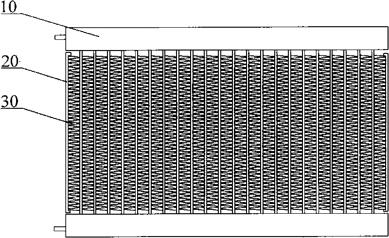
[0038] The core of the present invention is to provide a heat exchanger fin, which helps to reduce the difficulty of bending the heat exchanger along the direction of the header, and can also reduce the impact of the bending process on the heat transfer performance of the heat exchanger. The influence is minimized, so that it still maintains high heat transfer performance after bending. Another core of the present invention is to provide a heat exchanger comprising the above-mentioned fins.

[0039] In order to enable those skilled in the art to better understand the solution of the present invention, the present invention will be further described in detail below in conjunction with the accompanying drawings and specific embodiments.

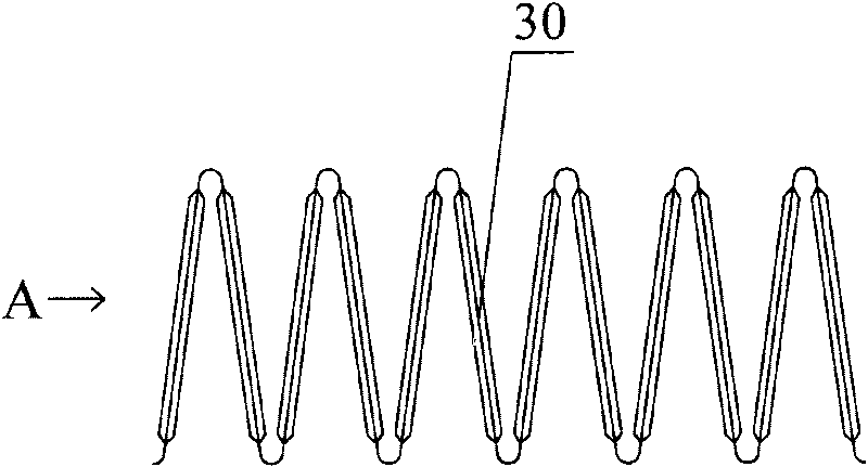
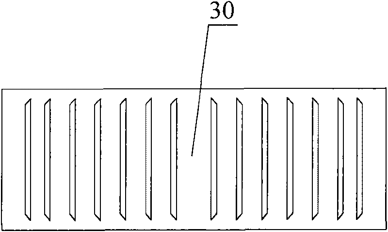
[0040] Please refer to Figure 5 , Figure 5 It is a structural schematic diagram of the first specific embodiment of the fin provided by the present invention.

[0041] The fin 100 in this specific embodiment is basically the same as the ex...


PUM


Abstract

The invention discloses a fin of a heat exchanger, which is arranged between neighboring flat pipes on a bent part of the heat exchanger. The fin can be bent on the bent part with the heat exchanger and is provided with a notch. The fin contributes to the reduction of the bending difficulty of the heat exchanger along a flow collecting pipe direction and can reduce the influence of a bending procedure on the heat exchanging performance of the heat exchanger to a minimum degree at the same time so as to still keep a relatively high exchanging performance after the fin is bent. The invention also discloses the heat exchanger with the fin.

Description

technical field [0001] The invention relates to a heat exchange equipment assembly, in particular to a fin located between flat tubes of a heat exchanger. The invention also relates to a heat exchanger comprising the above-mentioned fins. Background technique [0002] A heat exchanger is a device that transfers part of the heat of a hot fluid to a cold fluid, also known as a heat exchanger. It has a wide range of uses, for example, it can be used as a condenser, evaporator or heat pump in a refrigeration system. [0003] Please refer to figure 1 , figure 2 , image 3 , figure 1 It is a schematic diagram of the front structure of a conventional heat exchanger; figure 2 for figure 1 Schematic diagram of a group of fin structures of the shown heat exchanger; image 3 for figure 2 A view of the fin shown. [0004] The heat exchanger comprises a pair of headers 10, a plurality of parallel distributed flat tubes 20 and fins 30 arranged between adjacent flat tubes, the ...

Claims


Application Information

Patent Timeline
Patent Type & Authority Applications(China)
IPC IPC(8): F28F3/00
Inventor 刘华钊黄宁杰
Owner SANHUA HLDG GRP
Why Eureka
Try Eureka