Lubricating flow regulating device for dual-clutch automatic transmission

A technology of flow regulating device and automatic transmission, which is applied in the direction of transmission parts, gear lubrication/cooling, belt/chain/gear, etc., and can solve problems such as inability to accurately control lubrication flow, increased energy consumption of clutch dragging, and poor power economy.

Active Publication Date: 2017-08-25
CHONGQING TSINGSHAN IND
View PDF6 Cites 0 Cited by
  • Summary
  • Abstract
  • Description
  • Claims
  • Application Information

AI Technical Summary

Problems solved by technology

Therefore, it can only adjust the larger lubricating flow under high main pressure, and the ability to adjust the smaller or finer lubricating flow is weak, and it is impossible to accurately control the smaller lubricating flow. When no heat is generated and a large amount of lubricating flow is not required, a large lubricating flow is provided to the clutch instead, which increases the drag energy consumption of the clutch, which in turn leads to high fuel consumption of the vehicle and poor power economy of the vehicle

Method used


Image

  • Lubricating flow regulating device for dual-clutch automatic transmission

Examples


Embodiment Construction

[0014] Below in conjunction with accompanying drawing and specific embodiment the present invention is described in further detail;

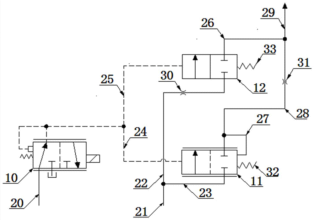
[0015] see figure 1 , the dual-clutch automatic transmission lubricating flow regulating device of the present invention comprises a proportional solenoid valve 10, a first lubricating valve 11, a pressure input oil circuit 20, a flow input oil circuit 21, a first oil circuit 22, a second oil circuit 23, a first The third oil passage 24, the fourth oil passage 25, the fifth oil passage 26, the sixth oil passage 27, the seventh oil passage 28, the eighth oil passage 29; the first damping hole 31; the first lubricating valve spring 32, the second oil passage The lubrication valve spring 33 , the first lubrication valve spring 32 is installed at the non-control end of the first lubrication valve 11 . from figure 1 It can be seen that the present invention also includes a second lubricating valve 12, a second lubricating valve spring 33 and a seco...


PUM


Abstract

The invention relates to a lubricating flow adjustment device for a double-clutch automatic transmission, which can accurately control the lubricating flow. A second lubricating valve spring is mounted at a non-control end of a second lubricating valve; a first lubricating valve is a pressure-reduction proportioning valve; the input end of a proportional electromagnetic valve is connected with a system pressure oil way and the output end of the proportional electromagnetic valve is connected with the control ends of the first lubricating valve and the second lubricating valve through a third oil way and a fourth oil way; one ends of a first oil way and a second oil way are connected with a flow input oil way; the other ends of the first oil way and the second oil way are connected with the input ends of the second lubricating valve and the first lubricating valve; one end of a seventh oil way is connected with the output end of the first lubricating valve; the other end of the seventh oil way is connected with one ends of a fifth oil way and an eighth oil way; the other ends of the fifth oil way and the eighth oil way are respectively connected with the output end of the second lubricating valve and clutches; a first damping hole is formed in the first oil way and the size of the hole diameter of the first damping hole is matched with the flow of oil in the first oil way; and a second damping hole is formed in the seventh oil way and the size of the hole diameter of the second damping hole is matched with the flow of oil in the seventh oil way.

Description

technical field [0001] The invention relates to a dual-clutch automatic transmission, in particular to a lubricating flow regulating device for a dual-clutch automatic transmission. Background technique [0002] An important function of the dual clutch in the dual clutch automatic transmission is that when the vehicle starts running continuously on a steep slope, one clutch is disengaged and the other clutch is engaged to make the automatic transmission operate normally to ensure that the vehicle can drive up and down. steep slope. During this process, the clutch friction plate will undergo a slipping phase, and the clutch will generate heat. The generation of this heat requires a lubricating flow regulating device to regulate lubricating oil to lubricate and cool the clutch. [0003] A common dual-clutch automatic transmission lubricating flow regulating device on the market, such as the DSG series products of Volkswagen, has only one proportional solenoid valve, one lubr...

Claims


Application Information

Patent Timeline
Patent Type & Authority Patents(China)
IPC IPC(8): F16H57/04
CPCF16H57/042F16H57/0434F16H57/0435
Inventor 周勇张本柱袁标
Owner CHONGQING TSINGSHAN IND
Why Eureka
Try Eureka