Hydraulically coupled electro-hydraulic brake system

A hydraulic braking and hydraulic coupling technology, which is applied in the direction of brakes, braking transmission devices, braking action starting devices, etc., can solve problems such as complex control algorithms, complex structures, and high motor performance requirements

Active Publication Date: 2019-01-11
JILIN UNIV
View PDF8 Cites 15 Cited by
  • Summary
  • Abstract
  • Description
  • Claims
  • Application Information

AI Technical Summary

Problems solved by technology

[0004] However, there are still some problems in the current electronic hydraulic braking system. The pedal force and brake booster are usually coupled through the reaction disc. When writing the control algorithm, it is necessary to consider various factors such as the deformation of the inner and outer rings of the reaction disc. The control algorithm is complex; in realizing decoupling When using a pedal feel simulator, the number of parts of the brake system is increased and the structure is complicated, and it is difficult for the pedal feel simulator to completely simulate the same pedal feel as the traditional vacuum booster brake system; many electronic hydraulic brake systems use a complete solution In the coupling scheme, the driver is only responsible for giving the braking intention during normal braking, and cannot make full use of the driver's pedal force, and because the driver's pedal force does not participate in the actual pressure building process, the braking pressure is completely controlled by the booster motor Established, the motor performance requirements are very high, there is a problem of excessive motor current, etc.

Method used


Image

  • Hydraulically coupled electro-hydraulic brake system
  • Hydraulically coupled electro-hydraulic brake system
  • Hydraulically coupled electro-hydraulic brake system

Examples


Embodiment Construction

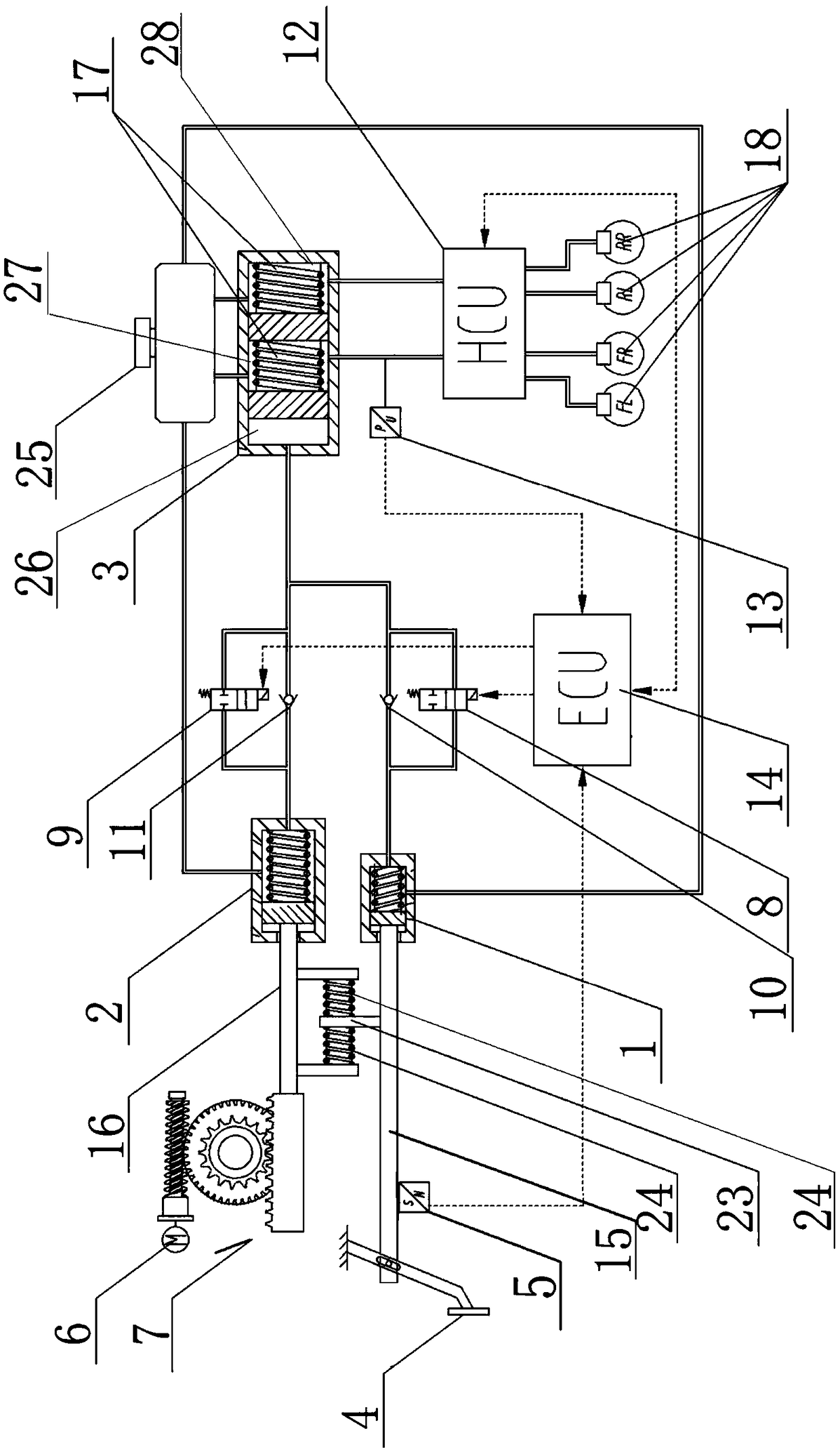
[0071] see Figure 1 to Figure 8 Shown:

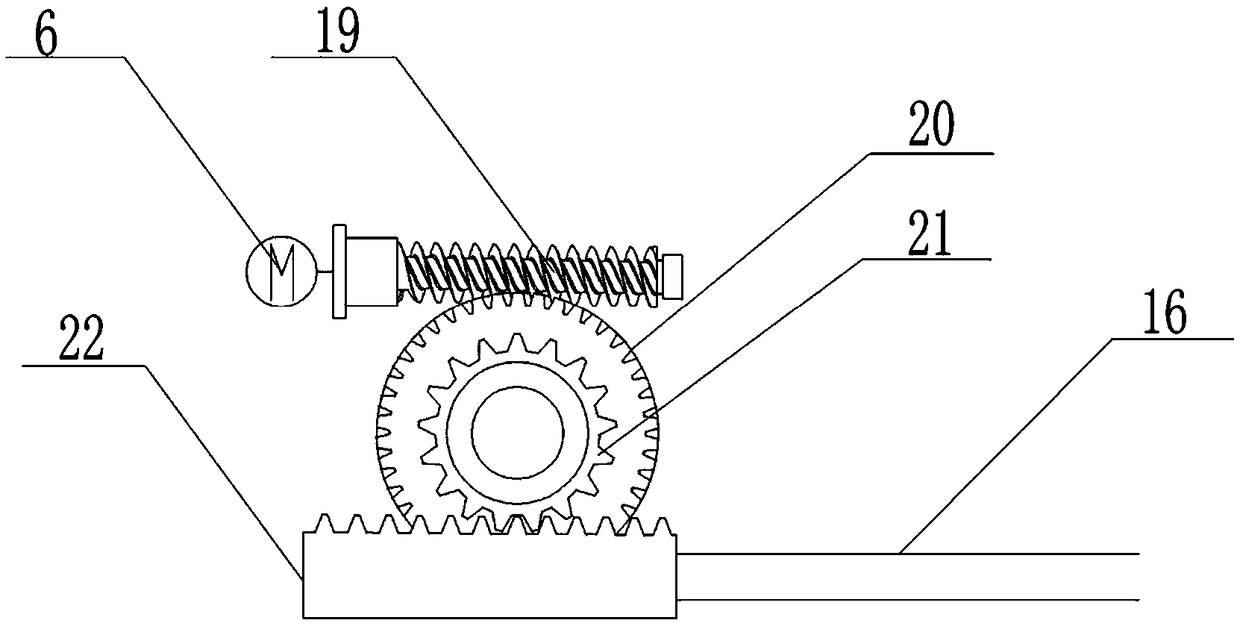
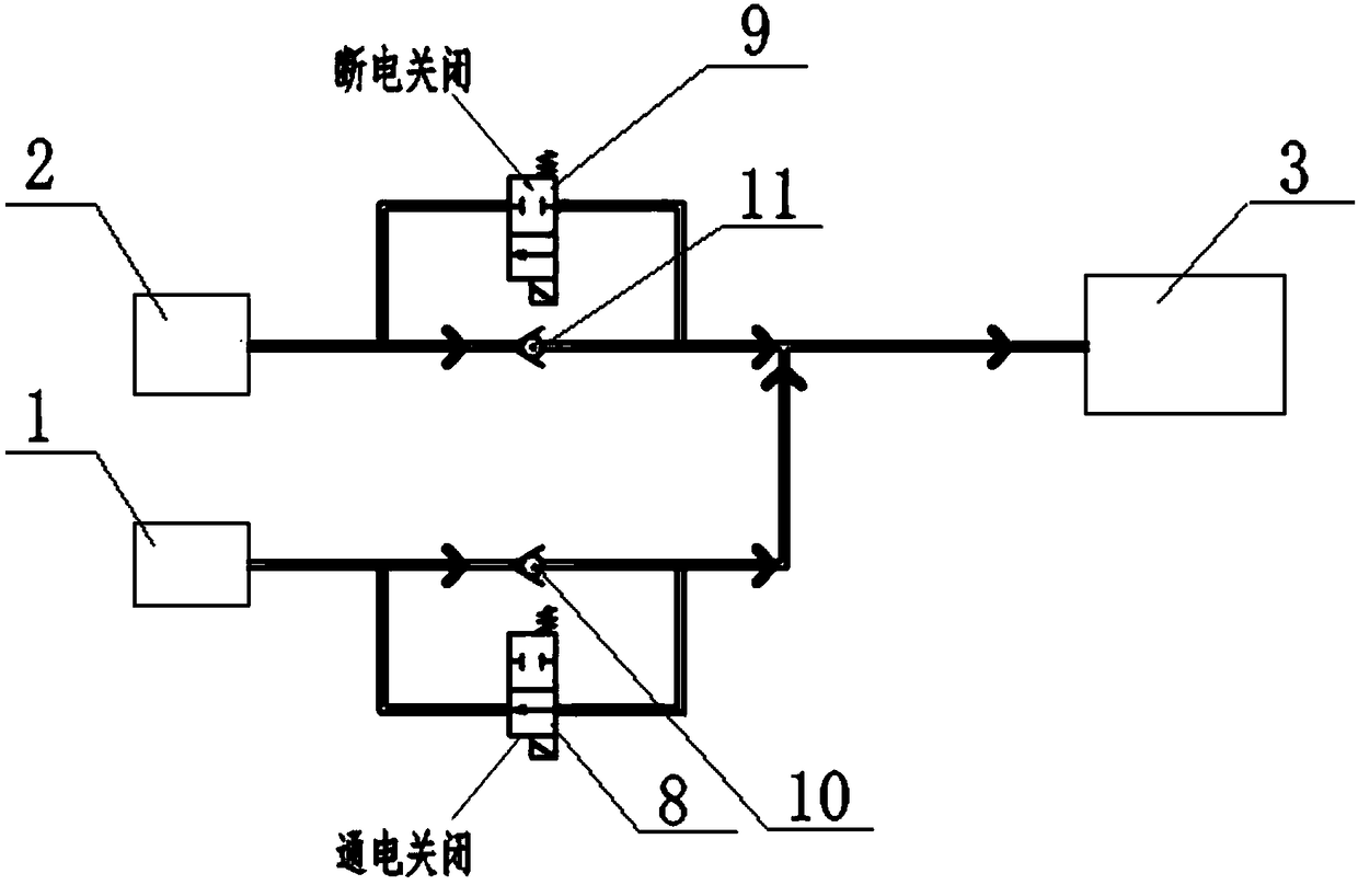
[0072] The present invention includes a human hydraulic cylinder 1, a booster hydraulic cylinder 2, a brake master cylinder 3, a brake pedal 4, a pedal stroke sensor 5, a booster motor 6, a booster transmission assembly 7, a normally open solenoid valve 8, a normally closed solenoid valve 9, Check valve A10, check valve B11, hydraulic control unit HCU12, hydraulic pressure sensor 13, electronic control unit ECU14:

[0073] The liquid outlet of the manpower hydraulic cylinder 1 is connected to the liquid inlet of the brake master cylinder 3 through a hydraulic pipeline, and the one-way valve A10 is arranged on the hydraulic pipeline between the manpower hydraulic cylinder 1 and the brake master cylinder 3, The normally open solenoid valve 8 is connected in parallel with the one-way valve A10 through the hydraulic pipeline, the brake pedal 4 is connected with the piston of the human hydraulic cylinder 1 through the pedal push rod 15, an...


PUM


Abstract

The present invention relates to a hydraulically coupled electro-hydraulic braking system, aiming at solving some problems existing in the current electro-hydraulic brake system. The hydraulically coupled electro-hydraulic braking system includes a manpower hydraulic cylinder, a booster cylinder, a brake master cylinder, brake pedal, pedal stroke sensor, booster motor, booster transmission assembly, normally open solenoid valve, normally closed solenoid valve, check valve A, check valve B, hydraulic control unit HCU, hydraulic pressure sensor, an electronic control unit ECU, and other structures. The hydraulically coupled electro-hydraulic braking system has three working modes of conventional braking, active braking and failure backup, and has the structure of hydraulic cylinder. The invention adopts a novel hydraulic coupling scheme, eliminates the reaction disk structure, the pedal force of the driver and the brake assisting force are coupled through the hydraulic mode, and the control algorithm of the whole brake system is simplified because the reaction disk structure is eliminated, and the control method is convenient to control.

Description

technical field [0001] The invention relates to a brake system, in particular to a hydraulic coupling electronic hydraulic brake system. Background technique [0002] With the continuous development of automobile electrification technology and intelligent technology, the traditional vacuum-assisted hydraulic braking system is difficult to meet the requirements of electric vehicles and smart vehicles for the braking system. Electric vehicles require the braking system to have a certain decoupling capability, that is, the decoupling of the brake pedal and the hydraulic braking force, so that the braking system can cooperate with regenerative braking, recover braking energy to the maximum extent, improve the cruising range of electric vehicles, and Guarantee the driver's pedal feeling in the decoupled state; intelligent cars require the brake system to have faster response speed, more precise brake pressure control and sufficient active braking capability, which can be implemen...

Claims


Application Information

Patent Timeline
Patent Type & Authority Applications(China)
IPC IPC(8): B60T7/04B60T13/74
CPCB60T13/748B60T7/042
Inventor 赵健宋东鉴朱冰赵文博田海舰雷鹏
Owner JILIN UNIV
Why Eureka
Try Eureka