

Reactive power compensation controller for power
A compensation controller and electric power technology, applied in reactive power compensation, reactive power adjustment/elimination/compensation, electrical components, etc., can solve problems such as insignificant compensation effect, uneven load distribution, hidden dangers of power grid operation, etc., to achieve Effects of reducing reactive power transmission flow, shortening reactive power transmission distance, and high-speed data communication capabilities
- Summary
- Abstract
- Description
- Claims
- Application Information
AI Technical Summary
Problems solved by technology
Method used
Image

Examples
Embodiment Construction
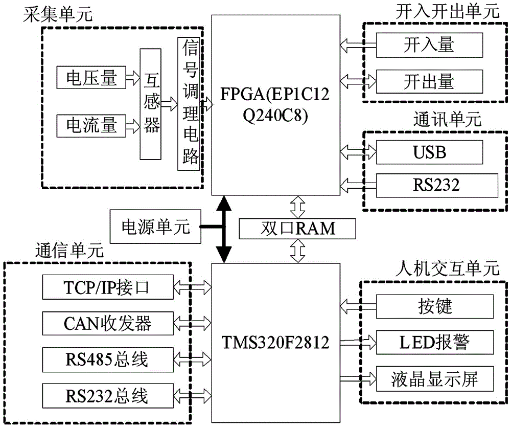
[0024] The invention is an electric reactive power compensation controller, in particular to the design of a reactive power compensation controller based on FPGA+DSP unit. It includes: power supply unit, FPGA+DSP unit, key input unit and liquid crystal display unit, communication unit, control unit. The FPGA+DSP unit structure can conveniently realize logic control and complex algorithm coordination control functions. The connection relationship is: the data acquisition unit, the input and output unit, the communication unit and the dual-port RAM unit are connected to the FPGA unit; the FPGA unit and the DSP unit realize data interaction through the dual-port RAM, and the multi-mode communication unit and human-computer interaction The unit is connected with the DSP unit; the button unit and the liquid crystal display unit communicate with the control unit to complete functions such as control parameter modification and control signal display; such a hardware structure can rea...
PUM
 Abstract
Description
Claims
Application Information