Equipment for guiding propping agents into underground fractured strata under drive of high-energy air flow

A technology of high-energy gas flow and proppant, which is applied in the direction of production fluid, wellbore/well components, earthwork drilling and production, etc. It can solve the problems that the fracturing effect is not obvious, the flow conductivity cannot be enhanced, and the high-energy gas fracturing effect cannot be controlled in real time, etc. question

Inactive Publication Date: 2014-10-29
ZHONGBEI UNIV
View PDF7 Cites 15 Cited by
  • Summary
  • Abstract
  • Description
  • Claims
  • Application Information

AI Technical Summary

Problems solved by technology

However, the disadvantage of this fracturing method is that, limited by the small downhole space, the charge amount is limited, the fracturing scale is small, and there is no proppant in the high-energy gas generated, which cannot support the fracturing fractures to enhance the conductivity. The fracture effect is not obvious, and the stimulation time is short because the fractures are closed due to the influence of in-situ stress
Moreover, the generation of high-energy gas in this method is carried out downhole, and it is impossible to control the amount of high-energy gas generated and its fracturing effect in real time

Method used


Image

  • Equipment for guiding propping agents into underground fractured strata under drive of high-energy air flow
  • Equipment for guiding propping agents into underground fractured strata under drive of high-energy air flow
  • Equipment for guiding propping agents into underground fractured strata under drive of high-energy air flow

Examples


Embodiment 1

[0029] Example 1. High-energy gas flow drives proppant into the equipment for downhole fracturing formation

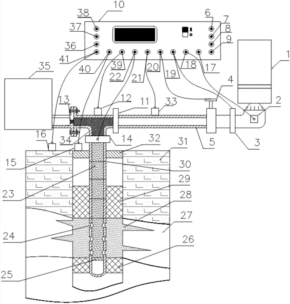
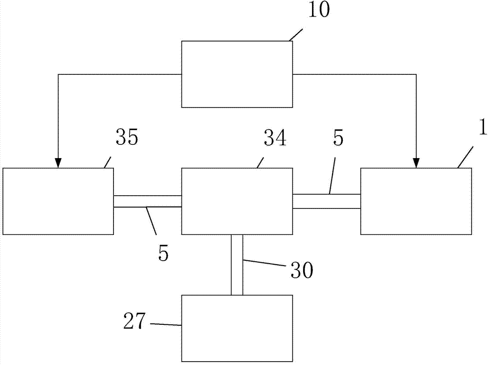
[0030] The high-energy gas flow-driven proppant introduced into downhole fracturing formation equipment in this example is a special equipment that uses high-energy gas flow to drive proppant fracturing formation. The specific structure of the equipment is as follows: Figure 1 to Figure 8 joint show, figure 1 The overall structure diagram of the equipment for driving proppant into the downhole fracturing formation by high-energy gas flow, figure 2 It is a block diagram of the equipment structure for high-energy gas flow driving proppant into downhole fracturing formation. In the two figures: 1 is the high-energy gas eruption mechanism, 2 is the nozzle temperature sensor, 3 is the nozzle flow sensor, 4 is the pressure relief valve, and 5 is the ground guidance Pipeline, 6 is the control end of the oxidant valve, 7 is the control end of the reducing agent valve, 8 is ...

Embodiment 2

[0031] Example 2. High-energy gas flow drives proppant into the equipment for downhole fracturing formation

[0032] The specific structure of the high-energy gas flow-driven proppant introduced into the downhole fracturing formation in this example is available Figure 1 to Figure 8 etc. have jointly shown that the equipment for introducing proppant into downhole fracturing formations driven by high-energy gas flow in this example differs from the equipment for introducing proppant into downhole fracturing formations driven by high-energy gas flow in Example 1. After the four fuels of fuel, catalyst and additive are sprayed into the high-energy gas combustion chamber in proportion and mixed, they can burn by themselves without ignition plug ignition. In this case, the high-energy gas combustion chamber may not be provided with an ignition plug and its control. 2. The main control microprocessor of this example selects and adopts the microprocessor of MSP430 type, or AVR type,...

Embodiment 3

[0033] Example 3. High-energy gas flow drives proppant into the equipment for downhole fracturing formation

[0034] The specific structure of the high-energy gas flow-driven proppant introduced into the downhole fracturing formation in this example is available Figure 1 to Figure 8 etc. have jointly shown that the equipment for introducing proppant into downhole fracturing formations driven by high-energy gas flow in this example differs from the equipment for introducing proppant into downhole fracturing formations driven by high-energy gas flow in Embodiments 1 and 2 in the following points: 1. In this example The oxidizing agent is liquid oxygen. The reducing agent of this example is selected to adopt hydrazine, or methylhydrazine, or unsymmetrical dimethylhydrazine, or mixed hydrazine-50. The catalyzer of this example selects and adopts ferric chloride hydrate etc. The additive of this example selects to adopt methyl alcohol or furfuryl alcohol. 2. The proppant of thi...


PUM


Abstract

The invention discloses equipment for guiding propping agents into underground fractured strata under the drive of high-energy air flow and belongs to the technical field of oil and gas reservoir fracture improvements. The equipment is composed of a high-energy gas spraying mechanism, a jet flow mechanism, a high-energy gas and jet flow mixing mechanism, a measurement control instrument and a guide pipeline in a combined mode. The measurement control instrument controls the high-energy gas spraying mechanism to ignite and spray high-energy gas, controls the jet flow mechanism to spray jet flow and controls the high-energy gas and the jet flow to generate a mixed fracturing medium in the mixing mechanism and enter the underground guide pipeline to arrive at a perforated hole of a target stratum for spraying; as a result, the target stratum generates three or more cracks, the propping agents are made to enter the cracks to support the target stratum, and consequently exploitation and production of oil and gas are facilitated. The equipment is reliable in running; the gas is used for fracturing without dependency on water resources; the fracturing scale is not limited; oxidizing agents, reducing agents and the like in use are universal commodities and are easy to obtain and safe in transportation and storage; reaction products of the oxidizing agents, the reducing agents and the like are clean and free of pollution, so that no damage is caused to the reservoir; the measurement control instrument is adopted to accurately control the pressure process, so that the underground fracturing effect is good, and the equipment is worth using and popularizing.

Description

technical field [0001] The equipment disclosed by the present invention for driving proppant into downhole fracturing formations belongs to the technical field of fracturing reconstruction of oil and gas reservoirs, and specifically relates to a special equipment for fracturing formations driven by high-energy airflow. Background technique [0002] At present, the fracturing technology widely used in downhole oil and gas wells is mainly hydraulic fracturing and high-energy gas fracturing based on downhole fracturing bombs. The hydraulic fracturing technology is: using a surface high-pressure pump set to inject high-viscosity fracturing fluid downhole through tubing , wherein the fracturing fluid is a solution in which thickeners, other chemicals and proppants are added to water. The surface high-pressure pump is pressurized so that the pressure of the fracturing fluid exceeds the in-situ stress of the rock formation to form fracturing cracks in the rock formation to real...

Claims


Application Information

Patent Timeline
Patent Type & Authority Applications(China)
IPC IPC(8): E21B43/267
Inventor 崔春生马铁华祖静裴东兴张红艳刘帅姚舜才范锦彪李新娥徐鹏沈大伟谢锐王燕尤文斌张艳兵梁志剑
Owner ZHONGBEI UNIV
Why Eureka
Try Eureka