Fully decoupled electro-hydraulic brake system

A technology of hydraulic braking and complete decoupling, applied in the direction of brakes, brake transmission devices, braking action starting devices, etc., can solve the problem of inability to actively control the pedal force of the driver, the high-pressure accumulator is afraid of vibration, and the maintenance cost is expensive. and other problems, to achieve the effect of simple structure, reduced leakage hidden danger, cost and maintenance cost.

Inactive Publication Date: 2019-01-11
JILIN UNIV
View PDF8 Cites 15 Cited by
  • Summary
  • Abstract
  • Description
  • Claims
  • Application Information

AI Technical Summary

Problems solved by technology

[0004] However, the current electronic hydraulic braking system generally adopts no decoupling or partial decoupling scheme, the decoupling ability is limited, the regenerative braking ability of electric vehicles cannot be fully utilized, and the braking energy can be recovered to the maximum; the driver's pedal force Reaction disk coupling is commonly used with electric power assist, and the deformation of the inner and outer rings of the reaction disk needs to be considered when designing the control algorithm. The control algorithm is relatively complicated; the current electronic hydraulic braking system is in the decoupled state. Usually, the pedal force compensation method or the pedal feeling simulator method is used, which cannot actively control the driver's pedal force; in addition, many electronic hydraulic braking systems still use high-pressure accumulators and motor pumps to control the hydraulic braking force. , but the structure of the high-pressure accumulator is relatively complex, the response time is slightly longer, and the high-pressure accumulator is afraid of vibration, there is a hidden danger of liquid leakage, the reliability is not high, the volume is large, the cost is high, and the maintenance cost is expensive

Method used


Image

  • Fully decoupled electro-hydraulic brake system
  • Fully decoupled electro-hydraulic brake system

Examples


Embodiment Construction

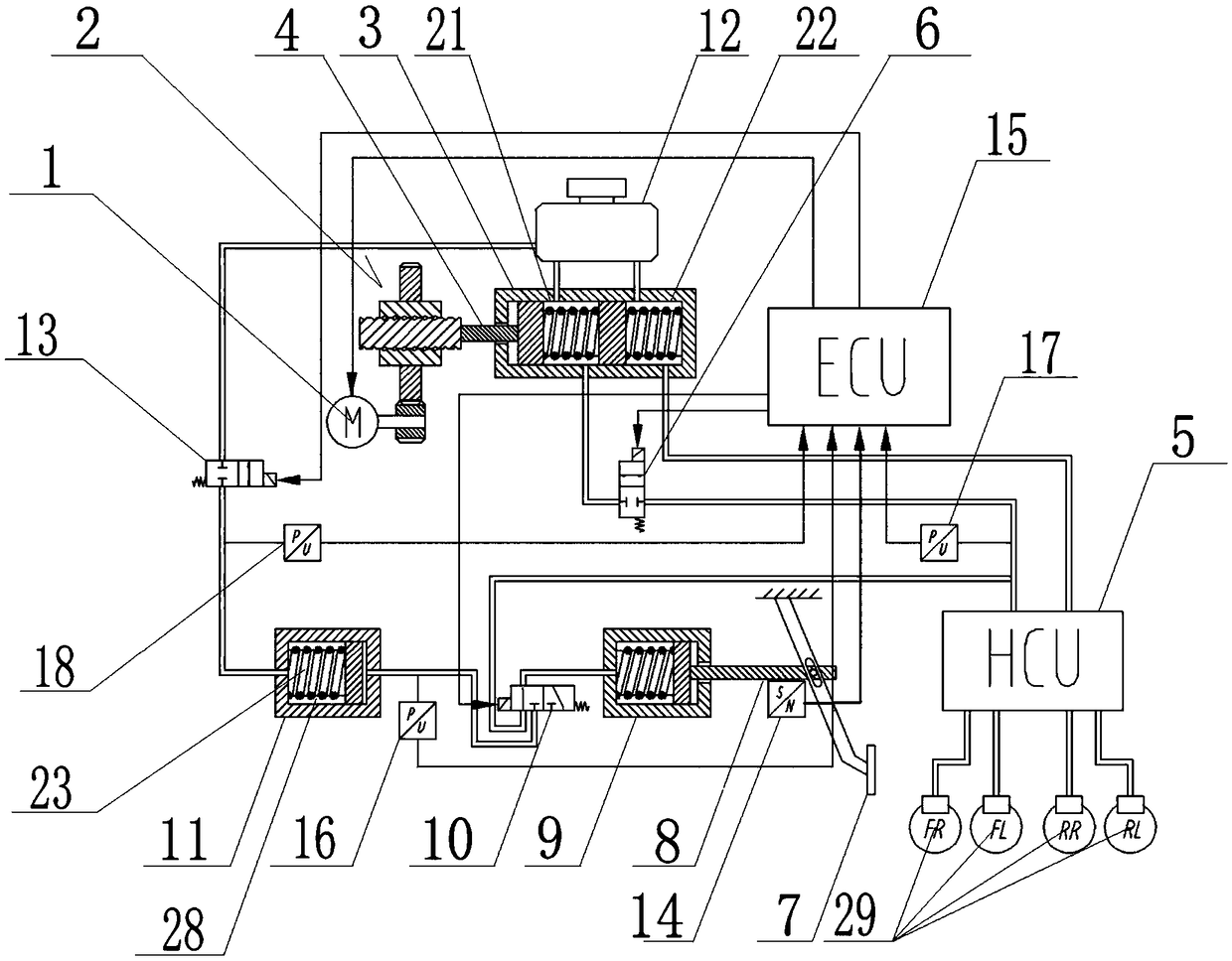
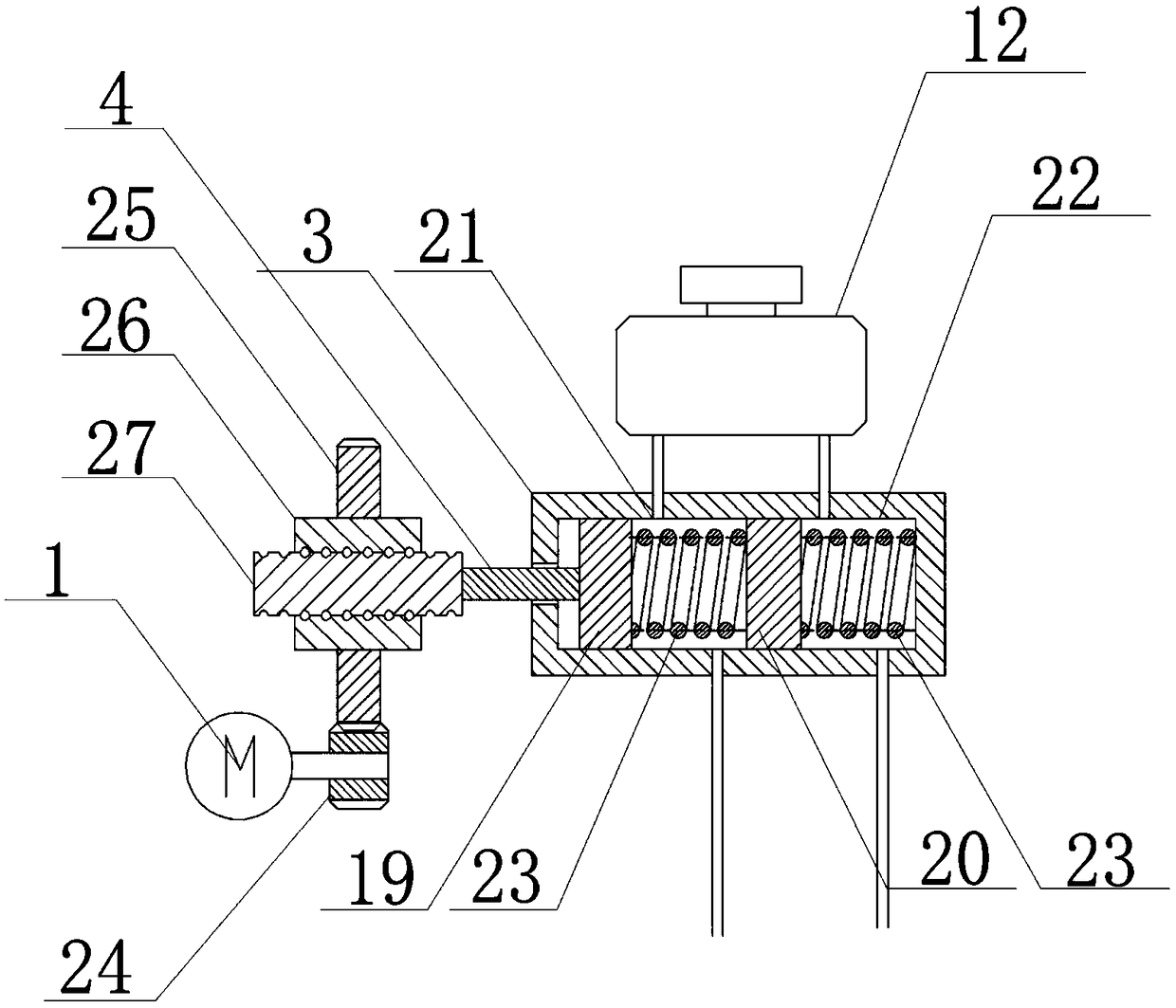
[0048] see Figure 1 to Figure 2 Shown:

[0049] The present invention includes a booster motor 1, a booster transmission assembly 2, a brake master cylinder 3, a piston push rod 4, a hydraulic control unit HCU5, a normally closed solenoid valve A6, a brake pedal 7, a pedal push rod 8, a human hydraulic cylinder 9, two Position three-way solenoid valve 10, pedal feeling simulator 11, liquid storage tank 12, normally closed solenoid valve B13, pedal stroke sensor 14 and electronic control unit ECU15:

[0050] The booster motor 1 is connected to the piston push rod 4 of the brake master cylinder 3 through the booster transmission assembly 2, the liquid outlet of the brake master cylinder 3 is connected to the hydraulic control unit HCU5 through a hydraulic pipeline, and the normally closed solenoid valve A6 is set to On the hydraulic pipeline connected between the brake master cylinder 3 and the hydraulic control unit HCU5;

[0051] The brake pedal 7 is connected to the piston...


PUM


Abstract

The present invention relates to a fully decoupled electro-hydraulic braking system, which comprises a booster motor, a booster transmission assembly, a brake master cylinder, a hydraulic control unitHCU, a normally closed solenoid valve A, a brake pedal, a pedal push rod, a human hydraulic cylinder, a two-position three-way solenoid valve, a pedal sensing simulator, a fluid reservoir, a normallyclosed solenoid valve B, a pedal stroke sensor and an electronic control unit ECU. The invention has three working modes of conventional braking, active braking and failure backup. The invention eliminates the structure of the high-pressure accumulator, adopts the motor driving and the mechanical structure driving, and has the advantages of simple structure, more reliable work, faster response speed, more accurate pressure control, and lower cost and maintenance cost. The invention adopts the scheme of complete decoupling, and can precisely control the hydraulic braking force through the booster motor, cooperate with the regenerative braking to recover the braking energy to the maximum extent, improve the range and comply with the development trend of the automobile electricization.

Description

technical field [0001] The invention relates to a brake system, in particular to a completely decoupled electronic hydraulic brake system. Background technique [0002] With the continuous development of automobile electrification and intelligent technology, automobiles put forward higher requirements for the braking system, which not only requires the braking system to provide sufficient braking performance and reliable braking safety, but also to be able to cooperate with regeneration Braking, to maximize the recovery of braking energy, improve the cruising range of electric vehicles, and have sufficient active braking capability, fast enough response, precise control of brake pressure, and can be used as an intelligent driving assistance system while improving safety At the same time, it is necessary to ensure a sufficiently comfortable driving and riding experience, and provide more intelligent and diversified driving modes. Traditional vacuum booster braking systems ar...

Claims


Application Information

Patent Timeline
Patent Type & Authority Applications(China)
IPC IPC(8): B60T7/04B60T13/74
CPCB60T13/748B60T7/042
Inventor 赵健宋东鉴朱冰赵文博邓志辉田海舰
Owner JILIN UNIV
Why Eureka
Try Eureka