
Graphite heat exchanger

A graphite heat exchanger, graphite technology, applied in the direction of heat exchanger types, heat exchanger shells, indirect heat exchangers, etc., can solve the problems of 0.3-0.5 MPa, low bending and tensile strength, maintenance and maintenance difficulties Large and other problems, to achieve the effect of improving service life, reducing impact and reducing vibration

Inactive Publication Date: 2016-01-06
NANTONG SHANJIAN GRAPHITE EQUIP
View PDF11 Cites 2 Cited by
  • Summary
  • Abstract
  • Description
  • Claims
  • Application Information

AI Technical Summary

Problems solved by technology

However, although the graphite heat exchanger has good corrosion resistance, the heat transfer surface is not easy to scale, and the heat transfer performance is good, but because the graphite material is a corrosion-resistant non-metallic material, the surface hardness is low, the graphite is easy to be brittle, and it is resistant to bending and tensile The strength is low, so it can only be used for low pressure. Even if the block pore structure with the best pressure bearing capacity, its working pressure is generally only 0.3 ~ 0.5 MPa
Therefore, the graphite heat exchange block is easily damaged by the long-term erosion of particles
Moreover, due to the vibration of the graphite heat exchanger in the working process, it is easy to cause damage to the graphite heat exchange tube, and it is difficult to maintain and maintain.

Method used


Image

  • Graphite heat exchanger
  • Graphite heat exchanger
  • Graphite heat exchanger

Examples


Embodiment Construction

[0018] The present invention will be further described below in conjunction with the accompanying drawings.

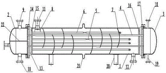
[0019] Such as figure 1 As shown, a graphite heat exchanger includes a cylinder body 1, a pipe box 2 is provided on one side of the cylinder body 1, and a head 3 is provided on the other side, and a tube plate is respectively provided between the cylinder body 1 and the pipe box 2 14 and tube sheet 15. There are tube sheets between the cylinder body 1 and the head 3 17 and tube sheet 16, tube sheet 14 and tube sheet 15 with tube sheet 17 and tube sheet Splitter plate 13 is arranged between 16, tube plate 14 and tube sheet Graphite heat exchange tubes 4 are arranged between 17, and a tie rod 5 is arranged inside the cylinder body 1, and a distance tube 6 is covered on the pull rod 5, and a baffle plate 7 is installed on the distance tube 6, and a water inlet 11 is provided at the upper end of the cylinder body 1 , The lower end of the cylinder is prov...


PUM


Abstract

The invention discloses a graphite heat exchanger. The graphite heat exchanger comprises a cylinder body, wherein a tube header is arranged on one side of the cylinder body, and an end socket is arranged on the other side of the cylinder body; a tube plate I and a tube plate II are arranged between the cylinder body and the tube header, a tube plate III and a tube plate IV are arranged between the cylinder body and the end socket, a spreader plate is arranged between the tube plate I and the tube plate II, and a spreader plate is arranged between the tube plate III and the tube plate IV; a graphite heat exchange tube is arranged between the tube plate I and the tube plate III; a pull rod is arranged in the cylinder body and sleeved with a tube spacer, and a baffle plate is installed on the tube spacer; a water inlet is formed in the upper end of the cylinder body, a water outlet is formed in the lower end of the cylinder body, and an anti-scour plate is arranged at the lower end of the water inlet. The graphite heat exchanger is reasonable in design and easy to operate. By means of the anti-scour plate, the impact of the water inlet on the heat exchange tube is reduced; by means of the interaction between the pull rod, the tube spacer and an expansion joint, vibration of the heat exchanger itself and vibration caused by external force are reduced, stress caused by temperature difference is reduced, and then the heat exchange tube is protected from damage, so that the service life of the heat exchanger is effectively prolonged.

Description

technical field [0001] The invention relates to a heat exchanger, in particular to a graphite heat exchanger. Background technique [0002] Graphite heat exchangers are heat exchangers whose heat transfer components are made of graphite. Graphite for manufacturing heat exchangers should be impermeable, and impregnated impermeable graphite and pressed impermeable graphite are commonly used. Graphite heat exchangers can be divided into three types according to their structure: block hole type, shell and tube type and plate type. Block hole type: assembled by several block graphite components with holes. Shell and tube type: Shell and tube heat exchangers occupy an important position in graphite heat exchangers, and are divided into two types: fixed type and floating head type according to the structure. Plate type: The plate heat exchanger is made of bonded graphite plates. In addition, there are immersion, spray and casing. [0003] During the use of the graphite heat ex...

Claims


Application Information

Patent Timeline
IPC IPC(8): F28D7/16F28F21/02F28F9/00
Inventor 姚松年黄晓东
Owner NANTONG SHANJIAN GRAPHITE EQUIP
Learn More