Supercharge Your Innovation With Domain-Expert AI Agents!

Control method of commodity transmission control system of vending machine

A technology of transmission control and control method, which is applied in the direction of coin-operated equipment for distributing discrete items, coin-operated equipment for distributing discrete items, coin-operated equipment for distributing discrete items, etc., which can solve the problem of beverage storage time Problems such as deterioration, cargo damage, and cargo jamming are achieved to ensure accuracy and improve stability

Active Publication Date: 2016-01-06
YANGZHOU JIEXING INTELLIGENT TECH CO LTD
View PDF6 Cites 4 Cited by
  • Summary
  • Abstract
  • Description
  • Claims
  • Application Information

AI Technical Summary

Problems solved by technology

[0007] The present invention designs an automatic vending machine goods transmission control system and its control method. The technical problems it solves are: (1) The goods are easily stuck when the existing vending machines are output, resulting in damage to the goods and mechanical failure. continuation of operations
(4) Because the replenishment method of existing vending machines is from the inside to the outside (and will not wait until sold out), the way the goods come out is from the outside to the inside. This way of delivery and replenishment will lead to The closer the vending machine is, the drinks inside will not be sold for a long time, which will have two adverse consequences. One of the drinks inside will deteriorate due to too long storage time, and the other is that the drinks with lower temperature inside cannot be sold in summer. give to consumers in need

Method used


Image

  • Control method of commodity transmission control system of vending machine
  • Control method of commodity transmission control system of vending machine
  • Control method of commodity transmission control system of vending machine

Examples


Embodiment Construction

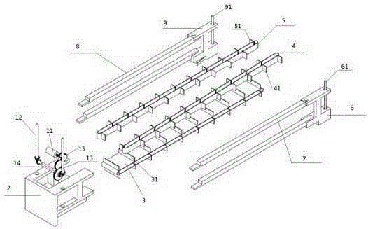
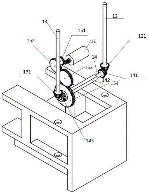
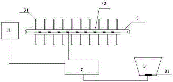
[0030] Combine below Figure 1 to Figure 3 , the present invention is further described:

[0031] Such as figure 1 and figure 2 As shown, a goods transmission control system for an automatic vending machine includes a transmission mechanism, a first conveyor belt 4, a second conveyor belt 5 and a supporting conveyor belt 3. Commodities are placed on the supporting conveyor belt 3, and the first conveyor belt 4 and the second conveyor belt The two conveyor belts 5 are respectively located on both sides of the commodity to protect the commodity from falling out of the supporting conveyor belt 3, the first conveyor belt 4, the second conveyor belt 5 and the supporting conveyor belt 3 are arranged in parallel, and their common end is provided with the transmission mechanism Drive them to rotate, and the common other end is the export port to output the goods.

[0032] A plurality of clips 31, 41, 51 are respectively provided on the first conveyor belt 4, the second conveyor be...


PUM


Abstract

The invention relates to a control method of a commodity transmission control system of a vending machine, wherein commodities are placed on a supporting conveyor belt (3). A first conveyor belt (4) and a second conveyor belt (5) are respectively arranged at two sides of the commodities for protecting the commodities from falling from the supporting conveyor belt (3). The first conveyor belt (4), the second conveyor belt (5) and the supporting conveyor belt (3) are arranged in parallel. One common end of the first conveyor belt (4), the second conveyor belt (5) and the supporting conveyor belt (3) is provided with a transmission mechanism for driving the first conveyor belt, the second conveyor belt and the supporting conveyor belt, and the other common end is used as a commodity outlet for outputting the commodity. A control unit compares a number which is measured by a pressure sensor on the supporting conveyor belt (3) with a number that is measured by a pressure sensor (B1) on the bottom of a commodity window funnel (B), thereby starting or stopping operation of the transmission mechanism. According to the control method of the invention, stopping of the transmission mechanism and the supporting conveyor belt is determined through numbers which are transmitted by the pressure sensors on the commodity window funnel and the supporting conveyor belt, thereby ensuring high accuracy in conveying the commodity out, and furthermore realizing high speed in informing maintenance personnel when a fault occurs.

Description

technical field [0001] The application date of this invention is October 21, 2013, the application number is: 201310493790.7, and the divisional application of the invention patent application entitled "A Vending Machine Goods Transmission Control System and Its Control Method". The invention relates to an automatic vending machine, in particular to an automatic vending machine goods transmission control system and a control method thereof. Background technique [0002] A vending machine (Vending Machine, VEM) is a machine that can automatically pay according to the coins put in. Vending machines are common equipment for commercial automation. They are not limited by time and place, can save manpower and facilitate transactions. It is a new form of commercial retail, also known as a 24-hour micro supermarket. [0003] At present, most of the vending machines are driven by the rotation control to output the goods, so it is easy to cause the goods to be stuck during the outp...

Claims


Application Information

Patent Timeline
Patent Type & Authority Applications(China)
IPC IPC(8): G07F11/00
CPCG07F11/007
Inventor 殷逢宝
Owner YANGZHOU JIEXING INTELLIGENT TECH CO LTD
Features
  • R&D
  • Intellectual Property
  • Life Sciences
  • Materials
  • Tech Scout
  • Unparalleled Data Quality
  • Higher Quality Content
  • 60% Fewer Hallucinations
Learn More