A Misoperation-preventing Isolation Switch Used in 110kv Power Network
An isolating switch and anti-error technology, which is applied in the direction of air switch components, circuits, electrical components, etc., can solve the problems of isolating switch ground knife misoperation, danger, controller error signal, etc., and achieve the effect of strengthening the degree of stability
- Summary
- Abstract
- Description
- Claims
- Application Information
AI Technical Summary
Problems solved by technology
Method used
Image
Examples
specific Embodiment 1
[0045] like figure 1 as shown,
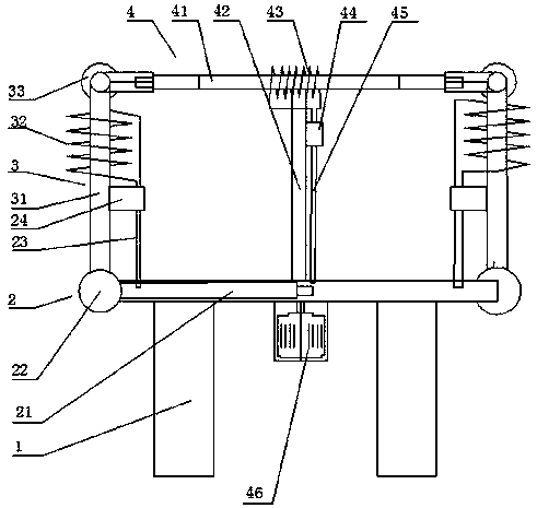
[0046] The invention discloses an error-proof isolating switch for a 110kV power grid, comprising a switch frame 1, a moving knife mechanism 4, a static knife mechanism 3, a ground knife mechanism 2, a moving knife electromagnetic mechanism 44, a ground knife electromagnetic mechanism 23, a moving knife Lock linkage mechanism, ground knife lock linkage mechanism, and switch self-locking mechanism, moving knife mechanism 4, static knife mechanism 3, ground knife mechanism 2 are arranged on switch frame 1, and moving knife electromagnetic mechanism 44 is arranged on moving knife mechanism 4 and uses For locking the moving knife mechanism 4, the ground knife electromagnetic mechanism 23 is set on the static knife mechanism 3 for locking the ground knife mechanism 2, and the moving knife lock linkage mechanism is connected in series on the ground knife mechanism 2 of the three-phase isolating switch, and the ground knife lock linkage mechanism It ...
specific Embodiment 2
[0053] Locking system based on implementing 1 disconnector, including:
[0054]The moving knife locking unit includes a 10kW-15kW moving knife motor 46, a 2m-2.2m long moving knife column 42, a 4m-4.5m long moving knife bar 41, a current sensor 43, a second electromagnetic lock, and a moving knife lock mechanism; The movable knife column 42 is vertically movably arranged at the middle or end of the switch frame 1, the movable knife bar 41 is horizontally arranged on the top of the movable knife column 42, and the movable knife motor 46 is connected to the bottom of the movable knife column 42, and the movable knife motor 46 rotates Drive the moving knife column 42 to rotate, the ratio of the rotating speed of the moving knife motor 46 to the rotating speed of the moving knife column 42 is 300-350, and the rotation angle of the moving knife column 42 is 0-95 degrees; the current sensor 43 is set on the moving knife bar 41 , the second induced current in the current sensor 43 is...
Embodiment 2
[0058] Based on the locking system of the isolating switch of embodiment 2, the control method of the isolating switch:
[0059] (1) When the isolating switch is working normally, the current sensor 43 senses the current on the movable knife rod 41. At this time, a second induced current of 30A-40A is generated in the secondary coil of the current sensor 43, and the second induced current passes through the wire It acts on the electromagnetic lock; in the second electromagnetic lock, a current is carried in the current induction coil;
[0060] (2) The second induction current of 30A-40A electrifies the second coil in the second electromagnetic lock, and the magnetic induction intensity generated by the second iron core wound by the second coil is 500T-600T; the moving knife lock tongue moves thereby Locking the moving knife unit cannot complete the disconnection action;
[0061] (3) After the second iron core has a magnetic field, pull or push the second bolt of the second el...
PUM
 Abstract
Description
Claims
Application Information
 - R&D
- Intellectual Property
- Life Sciences
- Materials
- Tech Scout
- Unparalleled Data Quality
- Higher Quality Content
- 60% Fewer Hallucinations
Browse by: Latest US Patents, China's latest patents, Technical Efficacy Thesaurus, Application Domain, Technology Topic, Popular Technical Reports.
© 2025 PatSnap. All rights reserved.Legal|Privacy policy|Modern Slavery Act Transparency Statement|Sitemap|About US| Contact US: help@patsnap.com

