Signal processing method and electronic equipment

A technology of electronic equipment and inductance, which is applied in the field of communication, can solve the problems of weak antenna radiation performance and ignore antenna radiation performance, and achieve the effect of high radiation performance

Inactive Publication Date: 2016-01-06
LENOVO (BEIJING) LTD
View PDF6 Cites 5 Cited by
  • Summary
  • Abstract
  • Description
  • Claims
  • Application Information

AI Technical Summary

Problems solved by technology

In related technologies, the standing wave ratio of the antenna is often emphasized, and the radiation performance of the antenna is ignored, resulting in weak radiation performance of the antenna when the broadband of the antenna is realized.

Method used


Image

  • Signal processing method and electronic equipment
  • Signal processing method and electronic equipment
  • Signal processing method and electronic equipment

Examples


Embodiment 1

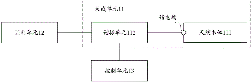
[0035] This embodiment records an electronic device, such as figure 1 As shown, the electronic device includes an antenna unit 11 and a matching unit 12; the antenna unit 11 includes an antenna body 111 and a resonance unit 112; wherein,

[0036] The matching unit 12 supports impedance matching to the antenna unit 11, the antenna body 111 itself supports receiving and / or sending signals of the first frequency band, and the antenna body 111 itself resonates at the center frequency of the first frequency band ;

[0037] The first end of the resonance unit 113 is connected to the feeding end of the antenna unit 11, and the second end of the resonance unit 113 is connected to the matching unit 12;

[0038] The electronic equipment also includes:

[0039] The control unit 13 is configured to receive a first instruction, the first instruction is an instruction indicating support for a second frequency band, and the center frequency of the second frequency band is different from th...

Embodiment 2

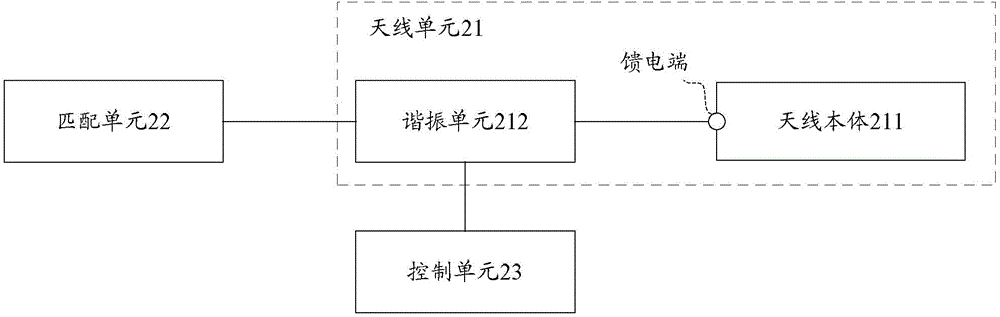
[0047] This embodiment records an electronic device, such as Figure 2a As shown, the electronic device includes an antenna unit 21 and a matching unit 22; the antenna unit 21 includes an antenna body 211 and a resonance unit 212; wherein,

[0048] The matching unit 22 supports impedance matching for the antenna unit 21, the antenna unit 21 itself supports receiving and / or sending signals of the first frequency band, and the antenna body 211 itself resonates at the center frequency of the first frequency band ;

[0049] The first end of the resonance unit 212 is connected to the feeding end of the antenna body 211, and the second end of the resonance unit 212 is connected to the matching unit 22;

[0050] The electronic equipment also includes:

[0051] The control unit 23 is configured to receive a first instruction, the first instruction is an instruction indicating support for a second frequency band, and the center frequency of the second frequency band is different from...

Embodiment 3

[0066] This embodiment records an electronic device, such as Figure 3a As shown, the electronic device includes an antenna unit 31 and a matching unit 32, and the antenna unit 31 includes an antenna body 311 and a resonance unit 312; wherein,

[0067] The matching unit 32 supports impedance matching for the antenna unit 31, the antenna body 311 itself supports receiving and / or sending signals of the first frequency band, and the antenna body 311 itself resonates at the center frequency of the first frequency band ;

[0068] The first end of the resonance unit 312 is connected to the feeding end of the antenna body 311, and the second end of the resonance unit 312 is connected to the matching unit 32;

[0069] The electronic equipment also includes:

[0070] The control unit 33 is configured to receive a first instruction, the first instruction is an instruction indicating support for a second frequency band, and the center frequency of the second frequency band is different...


PUM


Abstract

The invention discloses a signal processing method and electronic equipment. The method comprises steps of receiving a first instruction, wherein the first instruction is an instruction for indicating support of a second frequency range, and the center frequency of the second frequency range is different from that of a first frequency range; and responding to the first instruction, and controlling a resonance unit for adjusting self impedance, so that an antenna unit is enabled to resonate with the center frequency of the second frequency range, wherein the self impedance of the resonance unit presents inductance characteristics. The invention can support the antenna unit for working at multiple frequency ranges, and the radiation performance of the antenna unit at each frequency range is ensured.

Description

technical field [0001] The invention relates to communication technology, in particular to a signal processing method and electronic equipment. Background technique [0002] When the antenna environment in electronic equipment cannot meet the requirements of conventional antenna design, the common solution in the related art is to use a switch to switch the matching circuit to support different frequency bands, or use an adjustable capacitor to switch different frequency bands , to achieve the purpose of electronic equipment supporting broadband. [0003] However, the final performance of the antenna mainly depends on the standing wave ratio of the antenna (that is, the degree of matching) and the inherent radiation performance of the antenna. In the related art, the standing wave ratio of the antenna is often emphasized, and the radiation performance of the antenna is ignored, resulting in weak radiation performance of the antenna when realizing a wide frequency band of th...

Claims


Application Information

Patent Timeline
Patent Type & Authority Applications(China)
IPC IPC(8): H01Q23/00
Inventor 陈康康
Owner LENOVO (BEIJING) LTD
Why Eureka
Try Eureka