Novel analog low-pass filter circuit and design method

A technology of low-pass filter and design method, applied in electrical components, impedance network, multi-terminal network and other directions, can solve the problems of complex and difficult design process of low-pass filter, achieve simple and easy-to-understand implementation principle, improve design efficiency, The effect of reducing complexity

Pending Publication Date: 2022-04-05
合肥浩星科技有限公司
View PDF0 Cites 1 Cited by
  • Summary
  • Abstract
  • Description
  • Claims
  • Application Information

AI Technical Summary

Problems solved by technology

[0007] The purpose of the present invention is to provide a novel analog low-pass filter circuit and design method, which solves the complex and difficult design process of the existing low-pass filter, improves the adaptability of the filter circuit to changes in application conditions, and reduces the difficulty of product production. cost reduction

Method used


Image

  • Novel analog low-pass filter circuit and design method
  • Novel analog low-pass filter circuit and design method
  • Novel analog low-pass filter circuit and design method

Examples


Embodiment 1

[0071] Assuming that a low-pass filter needs to pass a signal of 80MHz, the three frequency points of harmonics 160MHz, 240MHz and 320MHz need to meet the suppression of more than 60dBc, and the suppression of the frequency point at 120MHz should meet 60dBc;

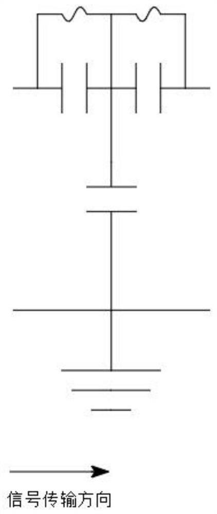
[0072] According to step S01 of the design method, set the characteristic impedance Z0 to 50 ohms, the cut-off frequency f0 to 90MHz, and f1 to 115MHz (higher than the cut-off frequency, close to 120MHz is beneficial to improve the suppression ability); by calculating the inductance value of the central circuit, it is calculated as 44.2 nH, the resonant capacitance is 43.3pF, and the capacitance to ground is 22.6pF; the actual values ​​are 47nH, 43pF and 22pF; the actual resonant frequency is about 112MHz calculated according to the resonant frequency formula of the parallel resonant circuit.

[0073] According to step S02 of the design method, combined with practical experience, the stop band suppression frequency points...

Embodiment 2

[0084] Assume that the frequency of the passing signal is adjusted to 60MHz in the previous design example, and the main suppression points are changed to 120MHz, 180MHz, and 240MHz.

[0085] According to step S01, the cut-off frequency is adjusted from 80 MHz to 60 MHz, and the relative frequency is decreased by about 0.75. First, adjust the resonant frequency of the original circuit from 112MHz to 84MHz, and the resonant inductance of the central circuit remains unchanged. According to formula 2 and formula 4, the new resonant capacitance value can be calculated to be about 76.5pF, and the ground capacitance of the central circuit is 38.25pF. Take the value 39pF.

[0086] According to step S02, the parameters of the original resonant inductance remain unchanged, and the resonant capacitance becomes 76.5pF, and the corresponding resonant frequency is calculated using formula 3 as:

[0087] The frequency point of 90MHz (originally 120MHz) corresponds to a resonance frequency ...

Embodiment 3

[0098] Assume that a low-pass filter needs to pass a signal of 100MHz to 150MHz, and it needs to meet the suppression of more than 60dBc for harmonics of 200MHz to 320MHz.

[0099] According to step S01 of the design method, set the characteristic impedance Z0 to 50 ohms, the cut-off frequency f0 to 160MHz, and f1 to 195MHz (higher than the cut-off frequency, close to 200MHz is beneficial to improve the suppression ability); by calculating the inductance value of the central circuit, it is calculated as 24.8 nH, the resonant capacitance is 26.8pF, and the ground capacitance is 12.4pF. The actual values ​​are 24nH, 27pF and 13pF. According to the resonant frequency formula of the parallel resonant circuit, the actual resonant frequency is about 197.8MHz.

[0100] According to step S02 of the design method, combined with practical experience, the stop band suppression frequency points are divided into 205MHz, 220MHz, 240MHz, 270MHz and 315MHz and other frequency points; the res...


PUM


Abstract

The invention discloses a novel analog low-pass filter circuit and a design method, and relates to the technical field of analog low-pass filters. The method comprises the following steps: step S01, determining passband cut-off frequency and characteristic impedance of a designed low-pass filter, calculating various parameters of a central circuit, and selecting parameter values close to calculated values; s02, determining the number of frequency points needing to be suppressed and corresponding frequency values, calculating various parameters of each stop-band suppression circuit, and selecting parameter values close to the calculated values; and S03, detecting the suppression effect of the low-pass filter. If the suppression is not satisfied, returning to the step S02, adjusting the related parameters until the suppression is satisfied, and finally completing the design of the low-pass filter. Low-pass filtering is realized by utilizing the characteristic that the impedance of the LC parallel resonance circuit is infinite, strict function constraint does not need to be obeyed, the design difficulty is reduced, and the efficiency is improved.

Description

technical field [0001] The invention belongs to the technical field of analog low-pass filters, in particular to a novel analog low-pass filter circuit and a design method. Background technique [0002] As a basic circuit for frequency selection or suppression processing in electronic circuits, the analog low-pass filter has been developed for hundreds of years. Other deformed filter circuits with functions such as high-pass, band-pass and band-stop can be evolved from it. After countless predecessors' research and analysis, the low-pass filter has been very mature and widely used. From its function type, it is mainly divided into Butterworth filter, Chebyshev filter, Bessel filter and elliptic filter. [0003] The traditional low-pass filter design method is to select the function type of the low-pass filter according to the needs, and then according to its normalized model, the parameters such as passband cut-off frequency, in-band fluctuation (ripple coefficient) and ou...

Claims


Application Information

Patent Timeline
Patent Type & Authority Applications(China)
IPC IPC(8): H03H7/01
Inventor 陈刚
Owner 合肥浩星科技有限公司
Why Eureka
Try Eureka