
Clutch system

A clutch device and locking technology, applied in the direction of clutch, friction clutch, mechanical drive clutch, etc., can solve the problem of reducing the separation force of the clutch device, and achieve the advantages of reduced weight and installation space, simple and cheap, and enhanced extrusion force. Effect

Inactive Publication Date: 2016-01-06
SCHAEFFLER TECH AG & CO KG
View PDF6 Cites 12 Cited by
  • Summary
  • Abstract
  • Description
  • Claims
  • Application Information

AI Technical Summary

Problems solved by technology

Many systems use the power of the drive train to achieve a reduction in the disengagement force of the clutch device

Method used


Image

  • Clutch system
  • Clutch system
  • Clutch system

Examples


Embodiment Construction

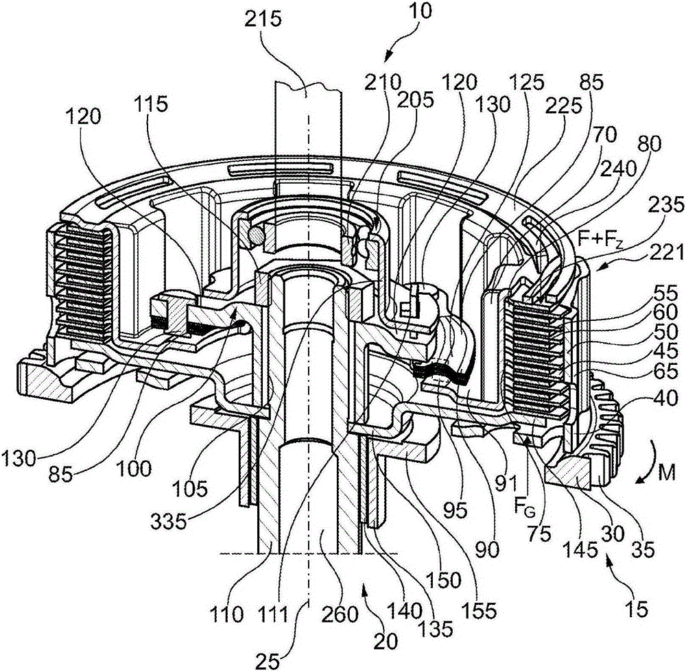
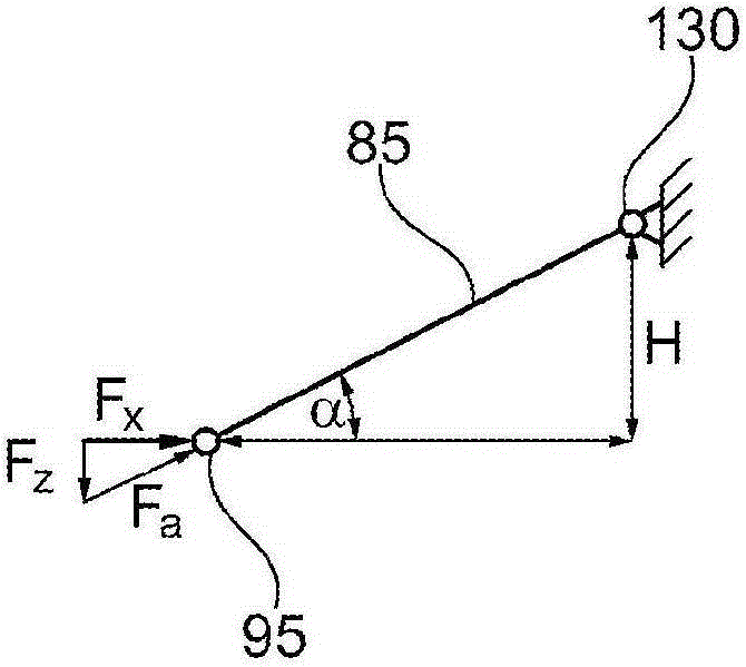
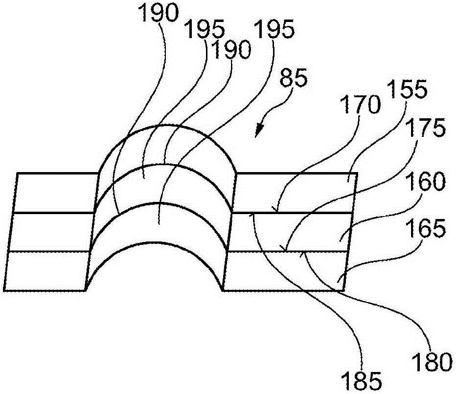
[0038] figure 1 A perspective half-sectional view of the clutch device 10 according to the first embodiment is shown. figure 2 shown in figure 1 A schematic illustration of the spring element 85 of the clutch device 10 shown in . image 3 shown in figure 1 A cross-sectional view of the clutch device 10 shown in . Figure 4 show Figures 1 to 3 A detailed view of the perspective cross-sectional view of the clutch device 10 shown in . Figure 5 A perspective sectional view of a clutch device according to a second embodiment is shown. Figure 6 A perspective cross-sectional view of the clutch device 10 is shown, and, Figure 7 and Figure 8 Shown with braced figure 1 A perspective illustration of the clutch device 10 is shown in . Figure 8 shown in Figure 7 A longitudinal sectional view of the clutch device 10 shown in . For ease of understanding, in the following the Figures 1 to 8 Let's explain together.

[0039] The clutch arrangement 10 includes an input side...


PUM


Abstract

The invention relates to a clutch system (10) comprising an input side (15) and an output side (20), which sides are arranged so as to be rotatable about a rotational axis (25), and at least one friction element (55) and at least one second friction element (60), the first friction element being connected to the input side for torque transmission, and the second friction element being connected to the output side for torque transmission. The first and the second friction element can be brought in frictional engagement with each other by a contact pressure to transmit torque between the input side and the output side, at least one spring element (85) being provided that is designed to boost the contact pressure.

Description

technical field [0001] The invention relates to a clutch arrangement having the features stated in the preamble of claim 1 . Background technique [0002] Customers expect better comfort and reliability from clutch units. In particular, especially in clutch devices for motorcycles, reducing the operating energy of the clutch device is one of the most important requirements because the clutch device is generally manually operated. Many systems achieve reduced clutch device disengagement force by using power from the drive train. The clutch device can be designed, for example, as a so-called booster clutch. This booster clutch consists of a pilot clutch and a main clutch, which are connected together via a ball ramp. The operation of the master clutch depends on the state of the driveline. Contents of the invention [0003] The object of the invention is to reduce the pressing force for closing the clutch arrangement. Furthermore, the object of the invention is to produ...

Claims


Application Information

Patent Timeline
Patent Type & Authority Applications(China)
IPC IPC(8): F16D13/54F16D13/58F16D13/56
CPCF16D13/56F16D2013/565
Inventor M·尚布里翁J·鲁夫
Owner SCHAEFFLER TECH AG & CO KG
Learn More