Electricity generation ship capable of comprehensively utilizing renewable energy sources

A renewable energy, power generation ship technology, applied in the field of ships, can solve the problems of water flow speed reduction, limitation, impossible to design water flow channels, etc., to achieve obvious effects and reduce emissions.

Active Publication Date: 2016-01-13
HARBIN ENG UNIV
View PDF5 Cites 34 Cited by
  • Summary
  • Abstract
  • Description
  • Claims
  • Application Information

AI Technical Summary

Problems solved by technology

However, the power generation of the hydro turbine generator only depends on the cross-sectional area of ​​the channel, the water speed in the channel and its power generation efficiency, and the power generation device will be completely limited by the hull
Moreover, only the lower part of the finned water wheel is submerged in the water and is washed by the water flow, so the finned water wheel cannot fully contact the water flow, and the finned water wheel cannot be fully utilized, and it is difficult to have a larger power generation
When the ship is large, it is impossible to design the water flow channel from the bow to the stern; one is that the longer water flow channel itself will reduce the water flow speed due to friction; the other is that even if the water flow channel is very long, it is not possible to install multiple generators , because the kinetic energy of the water is almost completely consumed by the first finned water wheel

Method used


Image

  • Electricity generation ship capable of comprehensively utilizing renewable energy sources
  • Electricity generation ship capable of comprehensively utilizing renewable energy sources
  • Electricity generation ship capable of comprehensively utilizing renewable energy sources

Examples


Embodiment approach 1

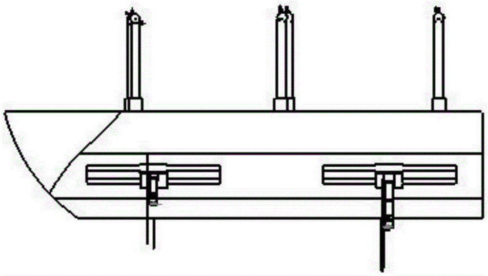
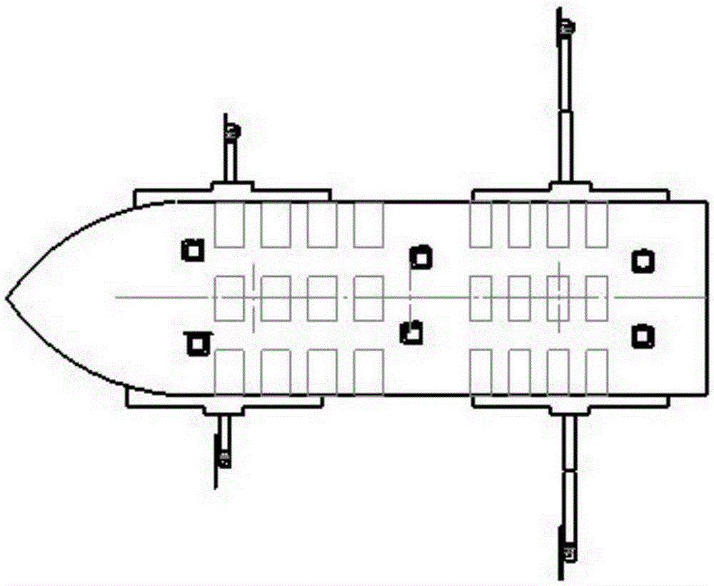
[0032] As shown in Figure 1, both sides of the hull are installed with such figure 2 The hydraulic telescopic arm 3 and the hydroelectric generator set (the water turbine comprising the blade 1 and the generator 2 ) are shown, and the hydroelectric generator set (the hydraulic turbine comprising the blade 1 and the generator 2 ) are installed at the end of the hydraulic telescopic arm 3 . The recovery hatch 5 is opened or closed by the hydraulic prop 4 . The hydraulic telescopic boom 3 is made up of multi-section telescopic booms, and each section telescopic boom can stretch out from the first section hydraulic boom in turn. One end of the hydraulic telescopic arm 3 is fixed in the recovery cabin.

[0033] Such as figure 2 with Figure 4 As shown, assuming that the bow of the ship faces the direction of the water flow, when power generation starts, the hydraulic prop 4 first opens the recovery hatch cover, then the hydraulic telescopic arm 3 slowly stretches out, and stop...

Embodiment approach 2

[0038] As shown in Figures 5, 6 and 7, in the second scheme, only the schematic diagram of the hydroelectric generating set (including the water turbine of the blade 22 and the generator 23) on one side of the hull is drawn, and the other side is completely symmetrical with this side. The ends of the hydraulic telescopic arms 17 on both sides of the hull are equipped with hydroelectric generators (hydraulic turbines and generators 23 comprising blades 22). When the ship is running, the hydroelectric generating set (including the water turbine of the blade 22 and the generator 23) and the hydraulic telescopic arm 17 are all located in the recovery cabin 18, and the recovery cabin door 16 is closed, and the recovery cabin door 16 is close to the hull, and can slide left and right to pass through the cabin. The opening and closing of the button control recovery hatch door 16 in the recovery hatch;

[0039] The hydraulic telescopic boom 17 is made up of multi-section telescopic bo...

Embodiment approach 3

[0048] As shown in Figures 8, 9, 10 and 11, in the third scheme, only the schematic diagram of the hydroelectric generating set (including the water turbine of the blade 26 and the generator 27) on one side of the hull is drawn, and the other side is completely symmetrical with this side . Among the figure, the support 28 of the hydroelectric generating set (including the water turbine of the blade 26 and the generator 27) is shorter than the support 39 of the hydroelectric generating set (including the hydraulic turbine of the blade 41 and the generator 42), and the support 39 has a knuckle to the water. This can prevent two hydroelectric generator blades on the same side from overlapping in a plane perpendicular to the water flow. The hydroelectric generator support can adopt the hollow support 28 and can also adopt the solid support 39, and each support meets the strength of supporting the hydroelectric generating set (including the water turbine of the blade 26 and the gen...


PUM


Abstract

The invention aims at providing an electricity generation ship capable of comprehensively utilizing renewable energy sources. The electricity generation ship comprises a photovoltaic electricity generation cell panel, a wind electricity generation set and a hydro electricity generation set, and independent photovoltaic electricity generation, wind electricity generation and hydro electricity generation can be carried out. The photovoltaic electricity generation cell panel, the wind electricity generation set and the hydro electricity generation set can be connected into a chip power grid at the same time for grid-connected electricity generation. When the hydro electricity generation set participates in electricity generation, a ship body is generally fixed, and a nose faces water flow. When only the photovoltaic electricity generation cell panel and the wind electricity generation set carry out electricity generation, the ship can run. Offshore wind energy, solar energy and tidal current energy are used for electricity generation to guarantee electricity in the initial stage of development of islands, and the ship can run to various islands and offshore platforms badly in need of electric energy to provide electric energy. Therefore, compared with other ships, the electricity generation ship is remarkable in effect of energy saving and emission reduction, and the emission of greenhouse gases is reduced to a large degree.

Description

technical field [0001] The invention relates to a ship, specifically a power generation ship. Background technique [0002] The development of marine resources has been increasingly valued by countries all over the world. my country currently has more than 6,000 islands to be developed. In order to speed up the initial development of islands, some electrical equipment such as motors and lighting are essential. It is very difficult, uneconomical and unrealistic to transport energy and electricity from land to remote islands. In addition, there are generally abundant renewable energy sources such as wind energy, solar energy, and tidal current energy around the island. [0003] For the patent application number CN200920273033, the patent titled the movable offshore new energy power platform discloses a mobile new energy power platform for comprehensive utilization of wind energy, wave energy and solar energy. Platform body, lifting pile, driving device for lifting pile, act...

Claims


Application Information

Patent Timeline
Patent Type & Authority Applications(China)
IPC IPC(8): F03D9/25F03B13/12H02S10/12B63B35/00
CPCY02A20/402Y02E10/50Y02E10/72Y02E10/727
Inventor 程鹏刘卫博兰海张敬南黄曼磊张强王钊孔祥玲杨新九喻凯
Owner HARBIN ENG UNIV
Why Eureka
Try Eureka