Experiment clamp with an angle adjusting function and a height adjusting function

A technology of height adjustment and angle adjustment, which is applied in angle/taper measurement, mechanical thickness measurement, etc., can solve problems such as unguaranteed accuracy, difficult position adjustment, labor-intensive efficiency, etc., to achieve low cost, improve test accuracy, save effect of space

Active Publication Date: 2016-01-13
CHERY AUTOMOBILE CO LTD
View PDF9 Cites 3 Cited by
  • Summary
  • Abstract
  • Description
  • Claims
  • Application Information

AI Technical Summary

Problems solved by technology

For those tests that only need to be loaded in one direction, it is easy to implement on the current test bench. It only needs to fix the structure through the fixture, and fix it to the test bench with metal pressure plates and bolts. Due to the single working condition, only one assembly is required. However, for some special structures and special test specification requirements, it is often necessary to load loads in several directions on a structure, such as the rear suspension mounting bracket structure in the form of a torsion beam, which bears loads in three directions Fx, Fy, and Fz. The loads in each direction need to be loaded separately. Due to the large volume of the hydraulic cylinder device for loading force in the laboratory, it is difficult to adjust the position. If you want to complete the test, you can only adjust the direction of the mounting bracket and the entire fixture structure before the start of each test. , the loading scheme in each direction must be assembled once and disassembled once, then the load in the three directions needs to be assembled three times and disassembled three times, which is laborious and inefficient, especially if the test needs to be loaded at a specific angle, such as the structure The direction of the force is 60°, so ordinary test fixtures cannot measure the angle, and only some auxiliary tools can be used to measure and determine the angle. Even if the auxiliary tools are used, it is difficult to determine the rotation point and it is difficult to ensure that it does not move, so the accuracy is also low. Can't be guaranteed, neither is the need for height adjustment

Method used


Image

  • Experiment clamp with an angle adjusting function and a height adjusting function
  • Experiment clamp with an angle adjusting function and a height adjusting function
  • Experiment clamp with an angle adjusting function and a height adjusting function

Examples


Embodiment Construction

[0037] Below in conjunction with accompanying drawing, the present invention will be further described:

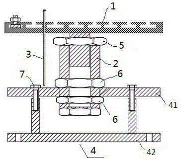
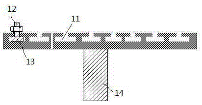
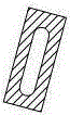
[0038] Figure 1 to Figure 9An experimental fixture with angle adjustment function and height adjustment function is shown, including a square plate 1 , a hollow bolt 2 , an angle pointer 3 , a fastening nut and a fixture body 4 . The square disc 1 is connected with the fixture main body 4 through the hollow bolt 2, and the square disc 1, the hollow bolt 2 and the fixture main body 4 can all rotate relative to each other. Angle and height relative to clamp body 4. The angle pointer 3 is arranged on the square disk 1 , and the angle scale is arranged on the fixture main body 4 to cooperate with the angle pointer 3 to display the angle through which the square disk 1 turns. The angle pointer 3 is also provided with a height scale line 31 . The structure of the hollow bolt 2 is as follows Figure 5 As shown, the outer cylindrical surface of the hollow bolt 2 is processed ...


PUM


Abstract

The invention relates to an experiment clamp with an angle adjusting function and a height adjusting function. The experiment clamp is characterized by comprising a fixed plate, connecting bolts and a clamp main body (4); a structure for experiment is arranged on the fixed plate; the fixed plate is connected to the clamp main body (4) through the connecting bolts, and the connecting places are fastened by fastening nuts; the fixed plate, the connecting bolts and the clamp main body (4) are in threaded connection in sequence; the angel and the height of the structure for experiment relative to the clamp main body (4) can be adjusted through the upward and downward movement and the rotary movement of the threaded connections; the clamp also comprises an angle pointer (3), and the angle pointer (3) is disposed on the fixed plate to match angle graduation lines on the clamp main body (4).

Description

technical field [0001] The invention belongs to the technical field of automobile test fixtures, and in particular relates to a test fixture with angle adjustment function and height adjustment function. Background technique [0002] In the automotive field, the strength and durability bench test is a very important link. According to different structural forms, the bench test can be divided into the whole vehicle bench test and the parts bench test. For the whole vehicle bench test It mainly includes 4-column, 12-channel and 24-channel tests, etc. The devices for these experiments generally do not need to be designed by the test engineer because the entire test bench is already included, such as the 24-channel testing machine of MTS, and there is no need to design fixtures by yourself. [0003] The opposite is true for component bench tests. In many cases, some small structural tests such as swing arms, mounting brackets, etc. need to design fixtures for fixing tests accord...

Claims


Application Information

Patent Timeline
Patent Type & Authority Applications(China)
IPC IPC(8): G01B5/24G01B5/06
Inventor 程凯梁厅张岩何选景
Owner CHERY AUTOMOBILE CO LTD
Why Eureka
Try Eureka