
Single-camera vision measurement method using concentric circle target for measuring position posture and rotating angle of object

A technology of monocular vision and measurement method, applied in the direction of photo interpretation, etc., can solve the problems of great influence of slope and large positioning error of image point of concentric circles.

Active Publication Date: 2016-01-13
ZHONGBEI UNIV
View PDF4 Cites 9 Cited by
  • Summary
  • Abstract
  • Description
  • Claims
  • Application Information

AI Technical Summary

Problems solved by technology

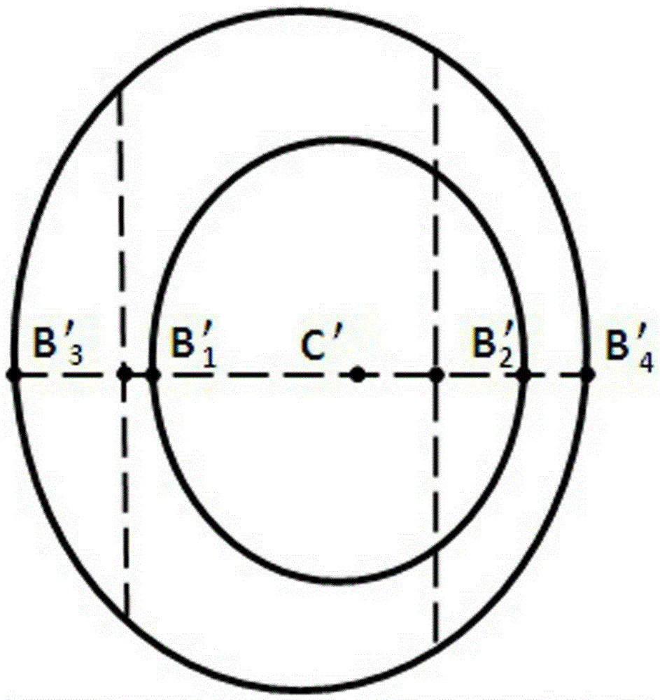
Because the centers of the two ellipses on the image plane are very close to each other, especially when the plane of the concentric circles is close to parallel to the image plane, the positioning error of finding the position of the center of the ellipse has a great influence on the slope of the straight line, which leads to the calculation of the image point position of the center of the concentric circles. The positioning error is also large

Method used


Image

  • Single-camera vision measurement method using concentric circle target for measuring position posture and rotating angle of object
  • Single-camera vision measurement method using concentric circle target for measuring position posture and rotating angle of object
  • Single-camera vision measurement method using concentric circle target for measuring position posture and rotating angle of object

Examples


Embodiment Construction

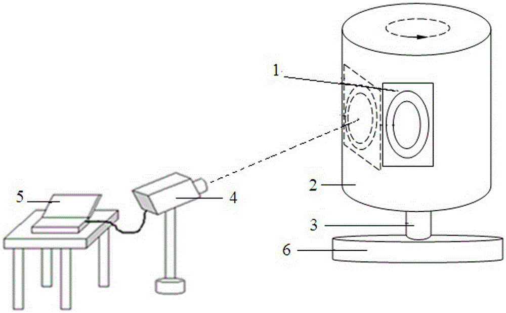
[0042] 1. Make a concentric circle target (1) by using concentric circles as marks on the target surface, and fix it on the object (2) parallel to the rotation axis (3) of the object to be measured (2). The rotating shaft (3) is installed on a base (6). Take pictures of the concentric circle target surface (1) with a digital camera (4) whose position and attitude remain unchanged. The image data of the digital camera (4) is transmitted to the computer (5) through the USB interface for processing.

[0043] 2. Use the sub-pixel precision image processing method we designed to process elliptical images to process photos of concentric circles, and use least squares fitting to find the equations of the two ellipses on the image plane:

[0044] Equation of the small ellipse: X 2 +b 1 XY+c 1 Y 2 +d 1 X+e 1 Y+f 1 =0(2-1)

[0045] Equation of the Great Ellipse: X 2 +b 2 XY+c 2 Y 2 +d 2 X+e 2 Y+f 2 =0(2-2)

[0046] The number of directions (A, B, C) of the normal vector...


PUM


Abstract

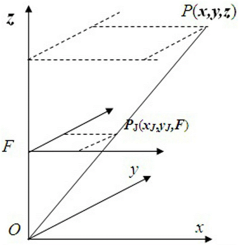
The invention discloses a single-camera vision measurement method using a concentric circle target for measuring the position posture and rotating angle of an object. The purpose is to determine the center image point position and position posture of a concentric circle rapidly and accurately. The concentric circle target is fixed to the object to be measured in parallel with a rotating shaft, a digital camera is used for shooting the target surface, and an image processing method of sub-pixel precision is used for processing a picture to obtain an equation of two ovals of an image surface; a resolving method that the coefficient of the equation of the ovals is utilized for solving the posture of the concentric circle is created; two chords of the ovals are utilized for creating a resolving method for solving the center image point position of the circle; the auxiliary characteristic diameter of the concentric circle is utilized for creating a resolving method for solving the focal length J of the camera with the pixel being a unit; in the resolving process, calculation is easy, precise and rapid; a computer simulation experiment result shows that the resolving methods are correct and practicable; the method can be used for calibrating angular displacement sensors of ailerons, wing flaps, a diving rudder and a rudder on a plane at an airport.

Description

technical field [0001] The invention relates to a monocular vision measurement method for measuring the relative position, posture and rotation angle of an object by using concentric circles as target surface marks, and belongs to the technical field of photoelectric measurement. Background technique [0002] Before the flight test of the aircraft, the angular displacement sensors of the ailerons, flaps, horizontal rudders and rudders on the aircraft need to be calibrated on the apron, and the monocular vision measurement method is required; in the final stage of spacecraft rendezvous and docking, tracking the spacecraft requires Use the monocular vision measurement method to independently measure the relative position and attitude of the target spacecraft; when hoisting large equipment, you can also use the monocular vision measurement method to monitor the position and attitude of the equipment in real time. The monocular vision measurement method has the advantages of non...

Claims


Application Information

Patent Timeline
IPC IPC(8): G01C11/04
CPCG01C11/04
Inventor 何森张旭峰王志斌曹美珍高永全刘运来董建会吴晶莹
Owner ZHONGBEI UNIV
Learn More