Component hole axis measurement method

A measuring method and technology of part holes, which are applied to measuring devices, instruments, and optical devices, etc., can solve the problems of inconvenient measuring process, occlusion of measuring light, large measuring error, etc., and achieve high accuracy of solution results, simple solution method, The effect of convenient manual operation

Active Publication Date: 2016-12-21
TSINGHUA UNIV
View PDF5 Cites 4 Cited by
  • Summary
  • Abstract
  • Description
  • Claims
  • Application Information

AI Technical Summary

Problems solved by technology

However, the laser tracker still has the following shortcomings for the axis measurement of large component holes: (1) The measurement error is relatively large. Due to the large size of large components and the complex environment of the assembly site, the laser tracker can only be placed at a relatively long distance. The shaft and hole are completely measured, and the increase of the measurement distance leads to a decrease in the measurement accuracy of the laser tracker; (1) the measurement process is very inconvenient, large parts are often complex in structure, and there are various tooling frames on the assembly site, all of which are It is easy to block the measurement light of the laser tracker, which brings inconvenience to the measurement process

Method used


Image

  • Component hole axis measurement method
  • Component hole axis measurement method
  • Component hole axis measurement method

Examples


Embodiment Construction

[0016] The method for measuring the axis of the part hole according to the present invention will be described in detail below with reference to the drawings.

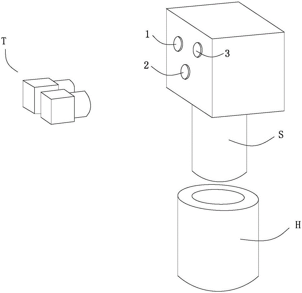
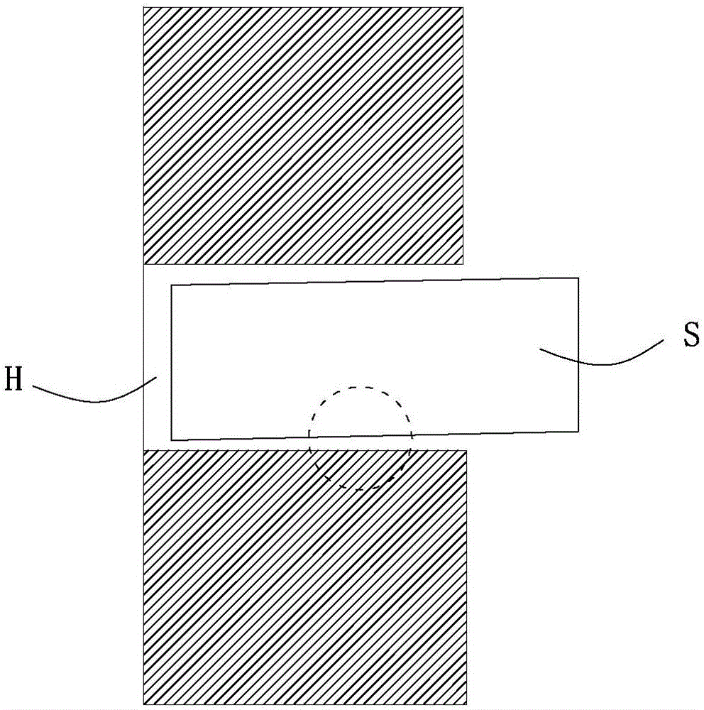
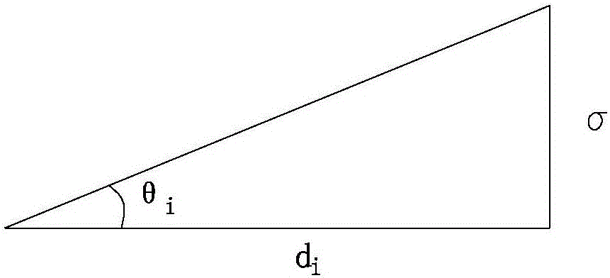
[0017] Reference Figure 1 to Figure 3 The method for measuring the axis of a part hole according to the present invention includes the following steps: S1, selecting a simulated shaft S that needs to be inserted into the hole H of the tested part, and the diameter of the simulated shaft S is smaller than the diameter of the hole H of the tested part, then The gap between the simulated axis S and the hole H of the tested part is recorded as σ; S2, at least three non-collinear mark points are set up on the simulated axis S, and the three-dimensional vision sensor T is used to track and measure each mark point; S3 , Establish a mark point coordinate system on the analog axis S, and calibrate the axis direction of the analog axis S The relationship with the coordinate system of the mark point; S4, gradually assemble the sel...


PUM


Abstract

The invention provides a component hole axis measurement method. The component hole axis measurement method comprises steps that S1, a simulation shaft is selected, and a diameter of the simulation shaft is smaller than a diameter of a measured component hole; S2, at least three non-collinear mark points are set on the simulation shaft, and a three-dimensional visual sensor is employed to track and measure the mark points; S3, a mark point coordinate system is established on the simulation shaft, and a relationship between an axis direction Vpi<rightarrow> of the simulation shaft and the mark point coordinate system is calibrated; S4, the selected simulation shaft is gradually assembled to the measured component hole, when the simulation shaft is inserted into the measured component hole at any depth di, the simulation shaft is obliquely turned around the axis of the measured component hole to a maximum allowable deviation angle thetai, thetai=sigma/di, and n groups of maximum simulation shaft allowable deviation angles thetai and corresponding axis directions Vpi<rightarrow> of the simulation shaft 2 are then acquired; and S5, on the basis of the data acquired in the step S4, an objective function described as the specification is constructed, and an optimal solution Vh<rightarrow> is solved when the objective function is the minimum. The method has advantages of convenient operation, high measurement precision and low cost.

Description

Technical field [0001] The invention relates to the field of assembly and measurement of large shaft hole components, in particular to a method for measuring the axis of a part hole. Background technique [0002] At present, the overall quality requirements of industrial products are getting higher and higher. In large-scale equipment manufacturing, the improvement of assembly quality is crucial to the overall quality of products. However, the existing manual assembly methods have higher requirements for workers, and it is difficult to achieve higher assembly accuracy requirements. Therefore, more and more automated assembly systems are used. [0003] Through research on published documents, patents, and industrial products, it is found that the shaft hole assembly of large parts in industrial applications needs to measure the axis direction of the hole in advance to determine the target position of the shaft. The existing measurement of the axis of the hole is mostly done by usi...

Claims


Application Information

Patent Timeline
Patent Type & Authority Applications(China)
IPC IPC(8): G01B11/27
CPCG01B11/27
Inventor 徐静万安陈恳
Owner TSINGHUA UNIV
Why Eureka
Try Eureka