
Magnetic inductive type rebound sensor

A magnetic induction and sensor technology, applied in the direction of testing the hardness of materials, can solve the problems of different maintenance cycles, induction failure, photoelectric tube dust, oil sensitivity, etc., and achieve the effect of long service life and accurate testing accuracy

Inactive Publication Date: 2016-01-13
BEIJING ZBL SCI & TECH
View PDF8 Cites 0 Cited by
  • Summary
  • Abstract
  • Description
  • Claims
  • Application Information

AI Technical Summary

Problems solved by technology

Although this kind of sensor is non-contact, wear-free, and has a long service life, it relies on light sensing. The biggest problem is that the photoelectric tube is sensitive to dust and oil. Errors or even sensor failures lead to wrong readings of the instrument. Manual maintenance is required to clean up the optical path. When the workload is heavy, it may even take a few days to clean up.
Because the principle of the grating device determines that the influence of dust and oil on it cannot be ignored, and the mechanical structure of the rebound meter determines that the grating device cannot be completely sealed and completely dust-proof and oil-proof, so this problem exists objectively. Some regular maintenance is necessary. Different brands of products have different maintenance cycles.

Method used


Image

  • Magnetic inductive type rebound sensor
  • Magnetic inductive type rebound sensor
  • Magnetic inductive type rebound sensor

Examples


Embodiment 1

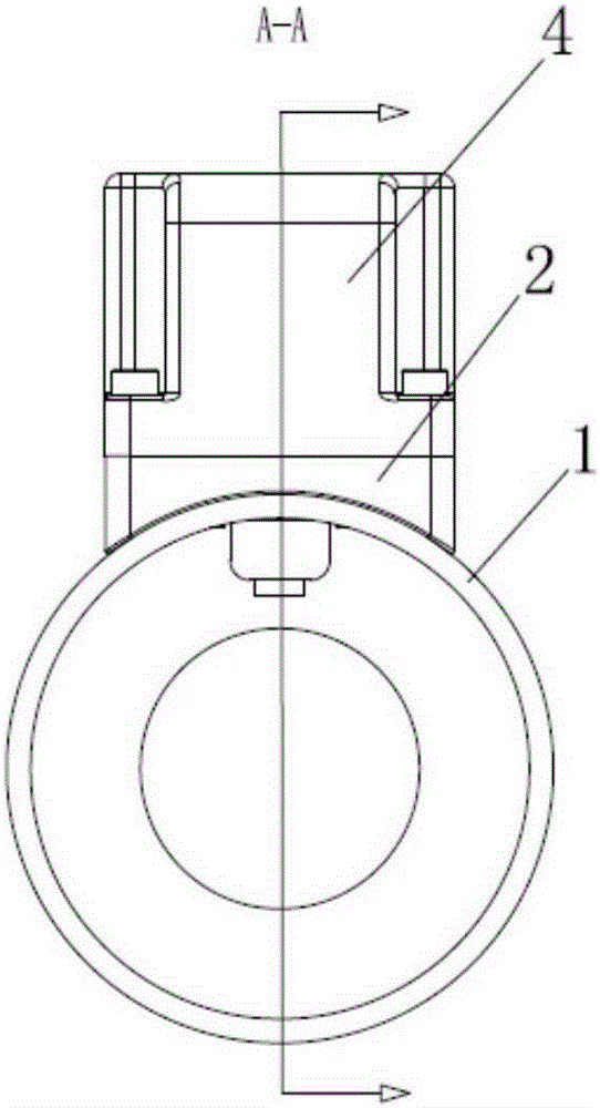
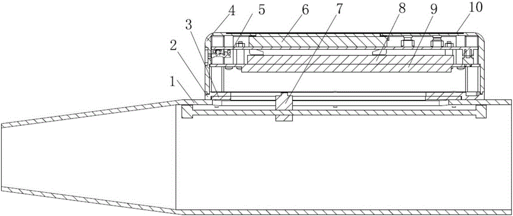
[0021] Such as Figure 1-3 Shown in detail, the present invention provides a magnetic induction rebound sensor, including a housing 1 with an upper housing 4 and a lower housing 2, the top surface of the upper housing 4 is provided with a display connected to the main board 5 screen 6, the main board 5 is provided with a control circuit and an acquisition circuit, the display screen 6 is provided with a film 10, the lower housing 2 is provided with a base 3 connected to the upper housing 4, and the base 3 is provided with There is a slider 7 capable of reciprocating movement, the slider 7 is connected with the hammer, the upper housing 4 is provided with a power supply 8, the power supply 8 is connected to the magnetic induction device, preferably the power supply 8 is a battery, and the magnetic induction The device includes a Hall sensor fixed on the slider 7, a magnetic strip 9 is arranged directly above the Hall sensor, and the slider 7 is preferably provided with a pointe...

Embodiment 2

[0024] Such as figure 1 , 2 As shown in and 4, the present invention provides a magnetic induction rebound sensor, including a housing 1 provided with an upper housing 4 and a lower housing 2, the top surface of the upper housing 4 is provided with a display connected to the main board 5 screen 6, the main board 5 is provided with a control circuit, the display screen 6 is provided with a film 10, the lower case 2 is provided with a base 3 connected to the upper case 4, and the base 3 is provided with a Moving slider 7, the upper housing 4 is provided with a power supply 8, the power supply 8 is connected to a magnetic induction device, and the magnetic induction device includes a miniature magnetic block fixed on the slider 7, and the miniature magnetic block A magnetic induction circuit 11 including several Hall sensors is arranged directly above, and the several Hall sensors are arranged in a matrix, preferably a linear array. In this embodiment, the miniature magnetic bl...


PUM


Abstract

The invention relates to the construction engineering testing technical field, and particularly relates to a magnetic inductive type rebound sensor. The magnetic inductive type rebound sensor provided by the invention includes a shell body comprising an upper shell body and a lower shell body; the upper shell body is provided with a display screen connected with a main board; the main board is provided with a control circuit and an acquisition circuit; the display screen is provided with a thin film; the lower shell body is provided with a pedestal connected with the upper shell body; the pedestal is provided with a sliding block, and the sliding block moves back and forth and is connected with a recoiling hammer; a power supply is connected with a magnetic inductive device and is fixedly mounted on Hall sensors on the sliding block, and the upper part of the Hall sensors is provided with a magnetic strip; the magnetic inductive device also includes a minisize magnetic block fixed on the sliding block, a magnetic inductive circuit comprising a plurality of Hall sensors is arranged right above the minisize magnetic block, and the Hall sensors are a linear array. The magnetic inductive type rebound sensor is realized by means of magnetic induction and is not afraid of disturbance of dust and oil stain, is in a non-contact mode, has no wear, is long in service life, has no need of maintenance at regular intervals, and has the advantages of being convenient, rapid, and accurate in measurement precision.

Description

technical field [0001] The invention relates to the technical field of construction engineering detection, in particular to a magnetic induction rebound sensor. Background technique [0002] The digital display rebound hammer in the prior art is equipped with a sensor on the original mechanical rebound hammer, which gets rid of the manual reading, and can automatically measure the rebound value through the sensor and its electronic circuit installed on the mechanical rebound hammer. Indication. [0003] CN2593183 discloses a mechatronic rebound hammer, which has a long cylindrical shell, and a bullet hammer with a weight is built in the shell, the bullet hammer is connected with the slider, and the slider slides on the slide bar, corresponding to There is a scale on the outer shell, and a wing-shaped pointer is horizontally connected between the ejection rod and the slider. There is a scale groove on the shell corresponding to the wing-shaped pointer, and the moving grid of...

Claims


Application Information

Patent Timeline
Patent Type & Authority Applications(China)
IPC IPC(8): G01N3/52
Inventor 郝冬妮封谊华赵山
Owner BEIJING ZBL SCI & TECH
Learn More