
Phase shifter dielectric plate and phase shifter

A medium plate and phase shifter technology, applied in the field of phase shifters, can solve the problems of abnormal transmission, large fluctuation of signal electrical indicators, and bumps in the movement of the medium plate, so as to achieve the effect of small contact area and small friction force.

Active Publication Date: 2016-01-13
COMBA TELECOM TECH (GUANGZHOU) CO LTD
View PDF3 Cites 6 Cited by
  • Summary
  • Abstract
  • Description
  • Claims
  • Application Information

AI Technical Summary

Problems solved by technology

[0004] Since there is a gap between the dielectric plate and the upper and lower inner walls of the cavity, if the gap is too small (for example, the dielectric plate is in contact with the top wall of the cavity), the pulling force required to move the dielectric plate will be too large, which will easily cause abnormal transmission and cannot make the signal linear. Phase difference; if the gap is too large, it will easily cause the dielectric board to bump up and down during the movement process, and the electrical index of the signal will fluctuate greatly

Method used


Image

  • Phase shifter dielectric plate and phase shifter
  • Phase shifter dielectric plate and phase shifter
  • Phase shifter dielectric plate and phase shifter

Examples


Embodiment Construction

[0029] The present invention will be further described below with reference to the accompanying drawings and exemplary embodiments, wherein the same reference numerals in the accompanying drawings all refer to the same components. Also, detailed descriptions of known arts will be omitted if they are unnecessary to illustrate the features of the present invention.

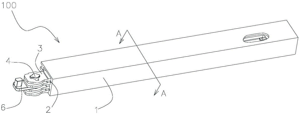
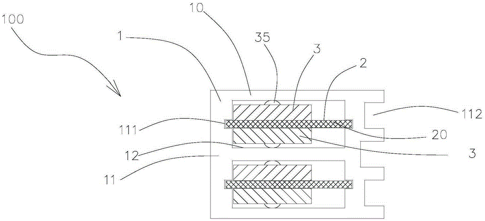
[0030] Figure 1-8 Commonly shows the phase shifter 100 of the present invention, comprising a cavity 1, a phase shifter circuit 2 disposed in the cavity 1 and a phase shifter dielectric plate 3 between the cavity 1 and the phase shifter circuit 2 (below Called "medium plate).

[0031] The cavity 1 includes a bottom wall 12, a pair of side walls 11 extending upward along both sides of the bottom wall 12 in the longitudinal direction, and a top wall 10 spanning the pair of side walls 11. At least one of the two lateral ends of the cavity 1 is The opening is used to install the circuit board 2 and the dielectric boa...


PUM


Abstract

The invention discloses a phase shifter dielectric plate, which is arranged between a phase shift circuit and a cavity and moves along a preset locus, wherein the dielectric plate is provided with a plurality of protrusions for pressing against the top wall or the bottom wall of the cavity, and the protrusions are higher than the plane of the dielectric plate. When the phase shifter dielectric plate is applied to a phase shifter, the dielectric plate is in tight fit with the cavity, and the problem of high signal index fluctuation in the moving process of the dielectric plate due to a large clearance between the dielectric plate and the cavity is solved; moreover, because the contact area between the protrusions and the cavity is small, high friction is not produced between the both, and abnormal transmission of the dielectric plate is avoided. In addition, the invention further discloses a phase shifter adopting the dielectric plate.

Description

【Technical field】 [0001] The invention relates to the technical field of communication devices, in particular to a phase shifter dielectric board and a phase shifter using the phase shifter dielectric board. 【Background technique】 [0002] In the coverage of mobile communication network, the electric adjustable base station antenna is one of the key equipment of the coverage network, and the phase shifter is the most core component of the electric adjustable base station antenna, the performance of the phase shifter directly determines the performance of the electric adjustable antenna , which in turn affects the coverage quality of the network, so the importance of the phase shifter in the field of mobile base station antennas is self-evident. [0003] The existing type of phase shifter mainly changes the propagation speed of the signal in the phase shifter by moving the medium in its cavity, so that the output signal flowing through the phase shifter forms a continuous lin...

Claims


Application Information

Patent Timeline
Patent Type & Authority Applications(China)
IPC IPC(8): H01P1/18H01Q3/32
Inventor 刘培涛陈礼涛邱建源其他发明人请求不公开姓名
Owner COMBA TELECOM TECH (GUANGZHOU) CO LTD
Learn More