
An enhanced heat dissipation liquid cooling radiator

A radiator and cooling liquid technology, applied in cooling/ventilation/heating transformation, etc., can solve the problems of increasing the flow resistance of liquid and the volume of the radiator, hot spots of heating components, and restricting the application of liquid-cooled radiators, etc. The effect of increased heat dissipation, improved efficiency, and reduced number of

Inactive Publication Date: 2017-06-30
TIANJIN UNIV OF COMMERCE
View PDF6 Cites 0 Cited by
  • Summary
  • Abstract
  • Description
  • Claims
  • Application Information

AI Technical Summary

Problems solved by technology

Traditional liquid cooling heat dissipation is mainly through processing a large number of heat-conducting ribs with different shapes on the bottom plate of the evaporator, which not only increases the flow resistance of the liquid and the volume of the radiator itself, but also increases the power consumption of the circulating pump, and heat transfer The effect is not good, and hot spots are prone to appear on the surface of heating components, which limits the further application of liquid cooling radiators

Method used


Image

  • An enhanced heat dissipation liquid cooling radiator
  • An enhanced heat dissipation liquid cooling radiator
  • An enhanced heat dissipation liquid cooling radiator

Examples


Embodiment Construction

[0018] The present invention will be described in further detail below in conjunction with the accompanying drawings and specific embodiments.

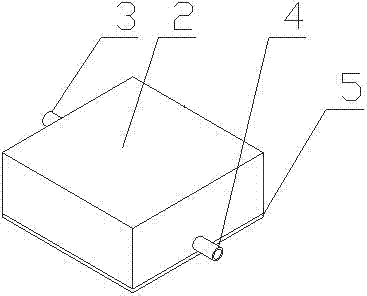
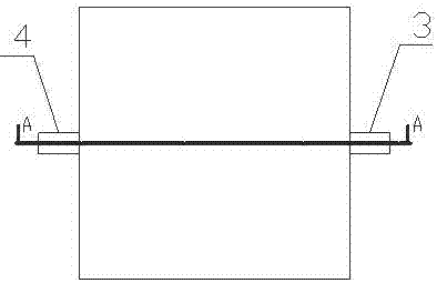
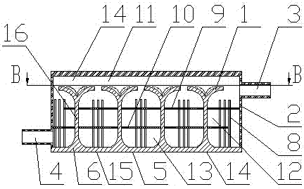
[0019] The schematic diagram of the enhanced heat dissipation liquid cooling radiator of the present invention is as follows Figure 1-Figure 5 As shown, it includes a sealed working chamber composed of a bottom plate 5 and an upper cover 2, the bottom of the upper cover 2 and the bottom plate 5 are fastened by welding or bolts, and the working chamber constitutes a space for circulating cooling medium. Inside the bottom plate 5 is an evaporation chamber 6 . The working chamber is provided with a plurality of cooling units, a plurality of rib columns 8 and a partition 9 parallel to the bottom plate 5, a first flow channel 11 is formed between the partition 9 and the top inner wall of the upper cover 2, A second flow channel 12 is formed between the partition plate 9 and the bottom plate 5, and the first flow channel 11 communicates w...


PUM


Abstract

The invention discloses a liquid-cooled radiator with enhanced heat dissipation, and aims to provide a liquid-cooled radiator which can effectively reduce the flow resistance and increase the heat dissipation per unit volume of the radiator. It includes a sealed working chamber composed of a bottom plate and an upper cover. The bottom plate is an evaporation chamber; there are multiple heat dissipation units, multiple rib columns and partitions parallel to the bottom plate in the working chamber. The first flow channel, the second flow channel is formed between the partition plate and the bottom plate, the first flow channel communicates with the second flow channel to form a coolant flow channel, and there is a liquid inlet on the upper cover opposite to the first flow channel, opposite to the second flow channel There is a liquid outlet on the upper cover; each heat dissipation unit is composed of a connected adiabatic chamber and a condensation chamber, the adiabatic chamber is located between the partition and the bottom plate, and the condensation chamber is located above the partition; the lower end of the adiabatic chamber communicates with the evaporation chamber; the bottom plate There are multiple rib columns that pass through the bulkhead. The heat sink can effectively maintain the temperature of the cooled device within a safe range, and realize the miniaturization of the heat sink.

Description

technical field [0001] The invention relates to the technical field of thermal energy engineering heat dissipation, in particular to a liquid cooling heat dissipation device used for heat dissipation of high heat flux density devices. Background technique [0002] With the increasing integration of electronic components, the heat dissipation of single equipment and the whole machine of high heat flux devices in the fields of electronic product equipment, aerospace, energy and chemical industry has increased sharply, and the cooling problem of high heat flux devices has become a constraint for related fields. The biggest obstacle to a technological leap. The traditional heat dissipation method is mainly based on air cooling, and other heat dissipation methods include liquid cooling, heat pipe heat dissipation, semiconductor refrigeration, and micro refrigeration system cooling. Among them, air cooling and liquid cooling are the most common and cheap cooling methods for high h...

Claims


Application Information

Patent Timeline
Patent Type & Authority Patents(China)
IPC IPC(8): H05K7/20
Inventor 耿凤彦杨洋陈萨如拉
Owner TIANJIN UNIV OF COMMERCE
Learn More