Laser welding system and method

A laser welding, laser technology, applied in laser welding equipment, lasers, welding equipment and other directions, can solve problems such as limiting the overall welding speed

Active Publication Date: 2016-01-13
PHOTON AUTOMATION
View PDF6 Cites 16 Cited by
  • Summary
  • Abstract
  • Description
  • Claims
  • Application Information

AI Technical Summary

Problems solved by technology

Therefore, for many precision welding methods it is often necessary to pulse the fiber laser at a frequency significantly greater than the travel time across the seam, which limits the overall welding speed using this method

Method used


Image

  • Laser welding system and method
  • Laser welding system and method
  • Laser welding system and method

Examples


Embodiment Construction

[0047] While the invention may take many different forms, for the purpose of facilitating an understanding of the principles of the invention, the invention will be described using specific language with reference to the embodiments shown in the drawings. It should be understood, however, that no limitation of the scope of the invention is thereby intended. Any changes and further modifications to the described embodiments, and any further applications of the principles described herein are considered to be within the normal range of those skilled in the art to which the invention pertains.

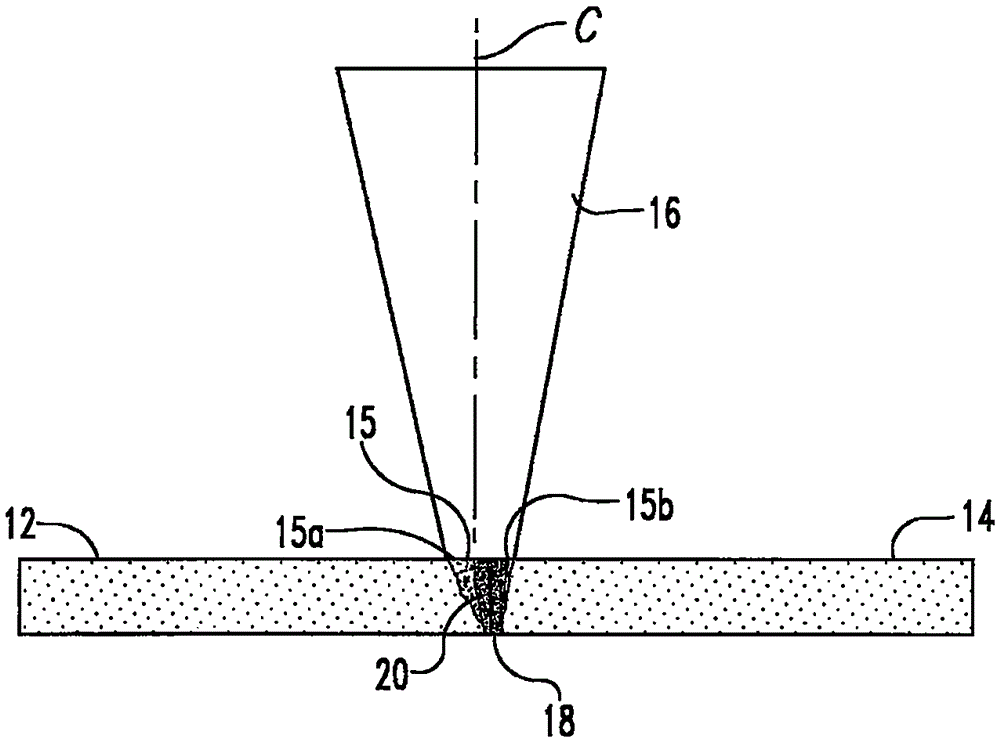
[0048] FIG. 1 shows a conventional method of laser welding dissimilar materials using a Nd:YAG laser 16 to weld a high melting point material 12 and a low melting point material 14 . A laser beam 16 is directed at the joint between the two materials. The beam spot 15 is large enough to span the small gap 18 at the material seam, one part 15a of the beam connects the high melting point ma...


PUM

PropertyMeasurementUnit
melting pointaaaaaaaaaa

Abstract

A system and method for precision welding using a fiber laser is disclosed in which varying intensity laser pulses are spread across the material junction in a number of high aspect ratio areas. The power density applied along each area is varied to accommodate differences in the material characteristics of each material while allowing for the creation of a more uniform weld pool alloy.

Description

[0001] relevant application data [0002] This application is a continuation-in-part of US Patent Application Serial No. 13 / 853,612, filed March 29, 2013. Background technique [0003] The present invention relates to laser control systems, and particularly, but not exclusively, to laser welding systems in which the power density is continuously varied based on the position of the beam at the portion to be welded. [0004] One of the most difficult challenges in laser welding two materials together is neutralizing the different melting points or thermal properties of the materials. A typical method of welding materials with dissimilar melting points or different thicknesses is to apply more energy to the material with the higher melting point. Traditionally, this has been accomplished by moving the laser beam parallel to the weld line while the center of the laser beam is offset from the weld line. Due to this offset, each laser spot falls more on one side of the weld line t...

Claims


Application Information

Patent Timeline
Patent Type & Authority Applications(China)
IPC IPC(8): B23K26/082B23K26/0622H01S3/067
CPCB23K26/0006B23K26/0869H01S3/067B23K26/24B23K26/082B23K26/323B23K2103/18B23K26/32B23K26/20
Inventor 理查德·E.·玛德二世
Owner PHOTON AUTOMATION
Why Eureka
Try Eureka