power transmission device

A technology of power transmission device and power input, which is applied in the direction of transmission device, multi-ratio transmission device, transmission device parts, etc., which can solve the problem of insufficient restraint, unable to reduce the resistance of lubricating oil stirring, and difficulty in accumulating chamber partition plate and Problems such as the tightness of the inner peripheral surface of the rib parts

Active Publication Date: 2018-04-06
AISIN AW CO LTD
View PDF7 Cites 0 Cited by
  • Summary
  • Abstract
  • Description
  • Claims
  • Application Information

AI Technical Summary

Problems solved by technology

[0004] However, in the power transmission device in the above-mentioned prior art, it is difficult to make the storage chamber partition plate and the inner peripheral surface of the bead member completely close to each other, and a gap is formed between the storage chamber partition plate and the inner peripheral surface of the casing. gap
Therefore, in the above-mentioned conventional power transmission device, it may not be possible to sufficiently suppress the flow of lubricating oil in the storage chamber from the gap between the storage chamber partition plate and the bead member and the interior of the storage chamber partition plate and the shell member. The gap in the peripheral surface flows into the differential chamber, and the agitation resistance of the lubricating oil acting on the ring gear of the differential device cannot be reduced.

Method used


Image

  • power transmission device
  • power transmission device
  • power transmission device

Examples


Embodiment Construction

[0034] Next, the mode of implementing the present invention will be described with reference to the drawings.

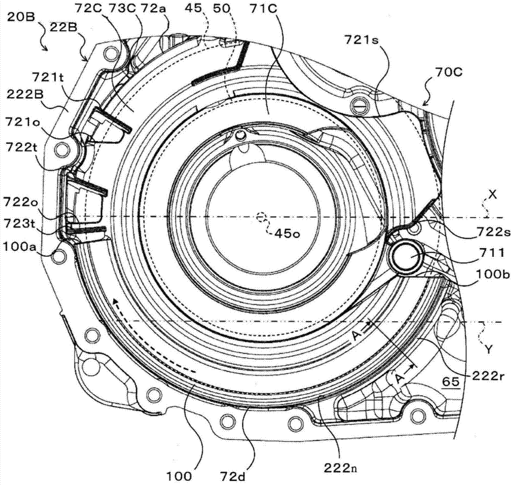
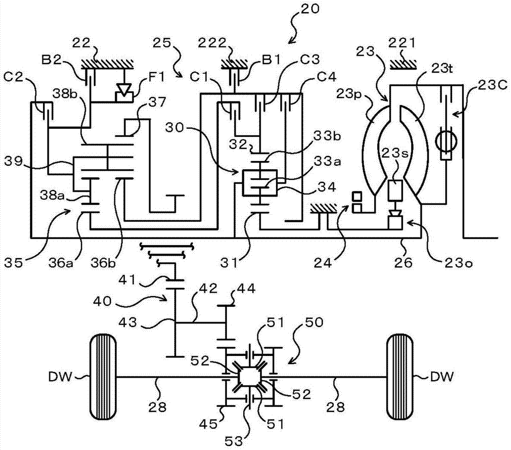
[0035] figure 1 It is a schematic configuration diagram of the power transmission device 20 of the present invention. figure 1 The illustrated power transmission device 20 is connected to a crankshaft of an engine (not shown) mounted on a front-wheel drive vehicle, and can transmit power from the engine to the left and right drive wheels (front wheels) DW. As shown in the figure, the power transmission device 20 has: a transmission housing 22 having a converter housing 221 (first housing) and a transaxle housing 222 (second housing) connected to the converter housing 221; a fluid transmission device (starter housing) Device), which is housed in the converter housing 221; the oil pump 24; the automatic transmission 25, which is housed in the drive axle housing 222; the gear mechanism (gear train) 40; the differential gear mechanism (differential mechanism) 50, etc.

[0036...


PUM


Abstract

The storage room partition plate (70) that divides the inside of the transmission case (22) into the differential chamber (60) and the working oil storage room (65) has a cylindrical portion (71) that covers the differential gear A part of the mechanism (50); the flange portion (72), which extends radially from the cylindrical portion (71); the differential ring gear surrounding portion (73), which extends from the outer peripheral portion of the flange portion (72) (72a) extends out and covers a part of the differential ring gear (45), the cylindrical portion (71), the flange portion (72) and the differential The movable ring gear surrounding part (73) is integrally formed between the transmission housing (22) and the outer peripheral edge part (72a) of the flange part (72), and at least in the range below the differential ring gear surrounding part (73) A sealing member (80) is arranged inside.

Description

Technical field [0001] The present invention relates to a power transmission device. The power transmission device has: a differential ring gear, which is arranged below a driving pinion on the input side and meshes with the driving pinion; a differential gear mechanism that is connected to the differential ring gear Gear connection; a housing, which houses a differential ring gear and a differential gear mechanism. Background technique [0002] In the prior art, as this kind of power transmission device, the following device is known, that is, the device has an intermediate shaft, a differential device (differential gear mechanism), a housing member, and a differential partition member, wherein the intermediate shaft It is arranged in parallel with the input shaft of the speed change mechanism; the differential device is arranged below the intermediate shaft and has a ring gear (differential ring gear) meshing with the output gear of the intermediate shaft; the housing component...

Claims


Application Information

Patent Timeline
Patent Type & Authority Patents(China)
IPC IPC(8): F16H57/04F16H57/029
CPCF16H3/663F16H57/0453F16H57/0483F16H2200/006F16H2200/0086F16H2200/2007F16H2200/2023F16H2200/2046F16H2200/2082F16H57/029F16H57/04F16H57/0402F16H57/0423F16H48/08F16H57/037
Inventor 鬼头昌士鸟居武史角田健太郎川村和也西久保僚辉山本慎也
Owner AISIN AW CO LTD
Why Eureka
Try Eureka