Radio frequency birdcage coil for mri guided radiotherapy

A technology of magnetic resonance imaging and radio frequency coils, applied in the field of RF coils

Inactive Publication Date: 2016-01-13
VIEWRAY TECH
View PDF8 Cites 5 Cited by
  • Summary
  • Abstract
  • Description
  • Claims
  • Application Information

AI Technical Summary

Problems solved by technology

Specifically, when MRI technology is applied to the field of radiotherapy, conventional birdcage coils are not ideally suited to accommodate the radiotherapy system

Method used


Image

  • Radio frequency birdcage coil for mri guided radiotherapy
  • Radio frequency birdcage coil for mri guided radiotherapy
  • Radio frequency birdcage coil for mri guided radiotherapy

Examples


Embodiment Construction

[0021] The following description presents embodiments by way of illustration and not limitation. Whether used with or without the word "about" or "approximately," and unless otherwise indicated, all numbers disclosed herein are approximations. When disclosing a numerical range having upper and lower limits, any number falling within that range is specifically and expressly disclosed.

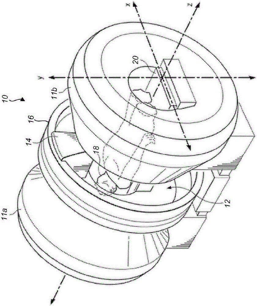
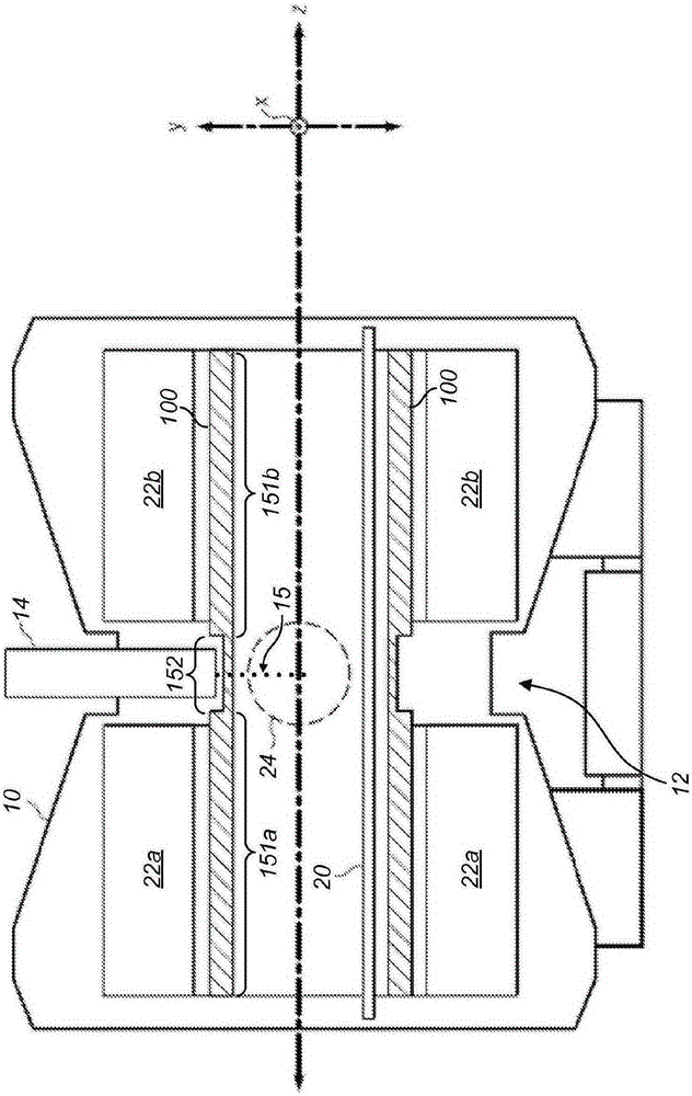
[0022] The RF coil assembly concept of the present disclosure can be used with any type of magnetic resonance imaging (MRI) system. It is particularly suitable for use with split solenoid or horizontal "open" MRIs, which include a gap between the two horizontal MRI magnet halves. The RF coil assembly disclosed herein is also suitable for use with a horizontal open MRI with additional instruments operating in its gap. figure 1 This arrangement is shown in which a horizontal open MRI 10 has first and second main magnet housings 11 a and 11 b separated by a gap region 12 . The instrument 14 is m...


PUM


Abstract

A radio frequency coil is disclosed that is suitable for use with a magnetic resonance imaging apparatus. The radio frequency coil comprises first and second conductive loops connected electrically to each other by a plurality of conductive rungs. The conductive rungs each include a section that is relatively thin that will result in less attenuation to a radiation beam than other thicker sections of the rungs. Insulating regions are also disposed in areas of the radio frequency coil that are bound by adjacent rungs and the conductive loops. Portions of the insulating regions can be configured to provide a substantially similar amount of attenuation to the radiation beam as the relatively thin sections of the conductive rungs.

Description

[0001] Cross References to Related Applications [0002] This PCT application claims priority to U.S. Patent Application Serial No. 13 / 796,784, filed March 12, 2013, and entitled "Radio Frequency Transmit Coil for Magnetic Resonance Imaging System," the filing date and entirety of which is hereby incorporated by reference in its entirety. technical field [0003] The present disclosure generally relates to radio frequency (RF) coils for use in magnetic resonance imaging (MRI) systems, including RF coils adapted for use with MRI-guided radiation therapy systems. Background technique [0004] In general, in an MRI system, a substantially uniform main magnetic field B is produced 0 to cover the entire area of ​​the object being imaged. The main magnetic field aligns the magnetic dipoles of the protons within the main magnetic field. Thereafter, a transient RF pulse is introduced to temporarily flip the proton dipole. Once the RF energy from the RF pulse is removed, the dipol...

Claims


Application Information

Patent Timeline
Patent Type & Authority Applications(China)
IPC IPC(8): G01R33/48
CPCG01R33/4808G01R33/481G01R33/4812G01R33/34076G01R33/34092
Inventor 詹姆士·F·登普西T·赫梅莱夫斯基
Owner VIEWRAY TECH
Why Eureka
Try Eureka