Sealing assembly assembling tool and method

A technology of sealing components and assembly tooling, applied in the direction of manufacturing tools, hand-held tools, etc., can solve the problems of non-metallic parts that cannot be fully filled, cannot be accurately positioned and centered, and cannot achieve positioning intentions, etc., to achieve compact structure and convenient operation , Ingenious design effect

Inactive Publication Date: 2016-01-20
AECC AVIATION POWER CO LTD
View PDF7 Cites 4 Cited by
  • Summary
  • Abstract
  • Description
  • Claims
  • Application Information

AI Technical Summary

Problems solved by technology

The purpose of the assembly fixture is to: (1) use the fixture base to position the metal parts, (2) set the non-metallic parts in the pin of the fixture punch, and use the taper surface of the front section of the punch pin to connect with the center hole of the metal part. The 60° conical surface positioning and centering method realizes the radial positioning of the non-metallic parts to realize the positioning of the assembly fixture, but there are some problems in the actual operation, and the positioning intention cannot be realized: (1) On the conical surface of the front end of the pin and the center hole of the end surface of the metal part The 60° cone is too short, resulting in unstable positioning; (2) The design drawings have requirements for the assembly temperature. In order to avoid the assembly temperature from falling beyond the specified temperature limit due to heat dissipation, the assembly operation must be fast and fast. When the front end of the punch is close to the metal part When the surface is centered, the non-metallic parts set on the punch pin will slide down to the large end surface of the metal part in advance before the punch is positioned, covering the position of the center hole, and the operator cannot accurately position and align in a hurry. In fact, the position of non-metallic parts has shifted to one side before press-fitting, and they are often pressed obliquely into the dovetail groove, resulting in the non-metallic parts not being able to fully fill the dovetail groove, or even not being pressed to the bottom of the groove. Quality hidden danger

Method used


Image

  • Sealing assembly assembling tool and method
  • Sealing assembly assembling tool and method
  • Sealing assembly assembling tool and method

Examples


Embodiment Construction

[0026] The present invention will be further described in detail below in conjunction with specific embodiments, which are explanations of the present invention rather than limitations.

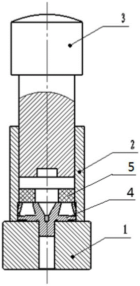
[0027] A sealing assembly assembly tooling of the present invention, such as image 3 As shown, it includes a base 1, a positioning sleeve 2 arranged on the upper end of the base 1, and a punch 3 sleeved in the positioning sleeve 2; the base 1 is provided with a positioning hole for placing the outer cylindrical surface of the small end of the metal part 4 The large end of the positioning sleeve 2 is used to be set on the large end outer cylindrical surface of the metal part 4, and the inner diameter of the small end is matched with the outer diameter of the non-metallic part 5; the stamping end of the punch 3 is a raised annular punch, The outer diameter of the punch 3 is the same as that of the non-metallic part 5 .

[0028] Wherein, the radial thickness of the ring in the punch 3 is great...


PUM


Abstract

The invention provides a sealing assembly assembling tool and method. The tool comprises a base, a positioning sleeve arranged at the upper end of the base in a matched manner, and a punch arranged in the positioning sleeve in a sleeved manner. The base is provided with a positioning hole used for containing a small end outer cylinder face of a metal component. The large end of the positioning sleeve is used for being arranged on a large end outer cylinder face of the metal component in a sleeving manner. The small end inner diameter part and the outer diameter part of a non-metal component are matched in a sleeved manner. The punching end of the punch is a protruding annular punch. The outer diameter of the punch is the same as the outer diameter of the non-metal component. The positions of to-be-assembled components in a clamp are limited by adding the positioning sleeve, the component base and the punch of the clamp and the two to-be-assembled components are connected through the positioning sleeve in series and are kept with the center consistency. The assembling defects caused by the fact that in an original assembly clamp, positioning elements are lacked, and the assembling positions of the to-be-assembled components are not determined are eliminated. The assembling requirement can be met, the design and concept are ingenious, and the structure is compact; and the manufacturing cost is low, using is easy, and operation is convenient.

Description

technical field [0001] The invention relates to an assembly of two different material assemblies, in particular to a sealing assembly assembly tool and method. Background technique [0002] The seal assembly is one of the important parts on the aero-engine, such as figure 1 shown. The sealing assembly is a new part formed by pressing non-metal parts (polytetrafluoroethylene) into the dovetail groove of the metal part. After assembly, the requirements: 1. The non-metal part must be completely filled in the metal part groove without any gap ;2. After the non-metallic parts and metal parts are press-fitted, the joints should be closely bonded without gaps. It is required that the metal and non-metallic surfaces meet, that is figure 1 Use a 10x magnifying glass to check A in the box, no gap greater than 0.1mm is allowed. [0003] For the assembly fixture that forms a new part by embedding parts of different materials, in the prior art, the metal part is put into the positioni...

Claims


Application Information

Patent Timeline
Patent Type & Authority Applications(China)
IPC IPC(8): B25B27/02
CPCB25B27/02B25B27/0092
Inventor 张玉环莫战海穆谦辛飞张亚军周晓卫李飞
Owner AECC AVIATION POWER CO LTD
Why Eureka
Try Eureka