Special cutter for specially-shaped angle

A cutting machine and special-shaped technology, which is applied in the field of special-shaped corner cutting machines, can solve the problems of inconvenient operation, tired hands, and poor cutting corner effects, etc., and achieve good cutting effect and easy and convenient operation process

Inactive Publication Date: 2016-01-20
江苏三达利建材科技有限公司
View PDF5 Cites 2 Cited by
  • Summary
  • Abstract
  • Description
  • Claims
  • Application Information

AI Technical Summary

Problems solved by technology

For the corners of the walls and pillars of the building, in order to decorate beautifully, it is necessary to chamfer the stones and tiles at the corners (see Figure 4 ), the current cutting machine can conveniently cut stones and tiles into regular squares

Method used


Image

  • Special cutter for specially-shaped angle
  • Special cutter for specially-shaped angle
  • Special cutter for specially-shaped angle

Examples


Embodiment Construction

[0021] The principles and features of the present invention are described below in conjunction with the accompanying drawings, and the examples given are only used to explain the present invention, and are not intended to limit the scope of the present invention.

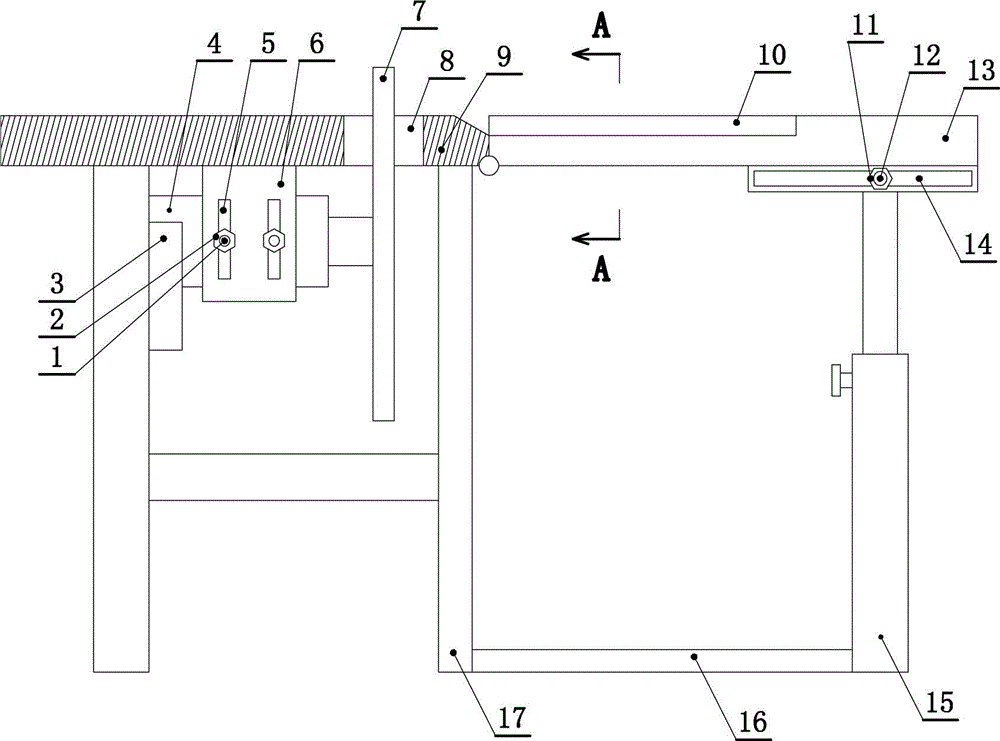
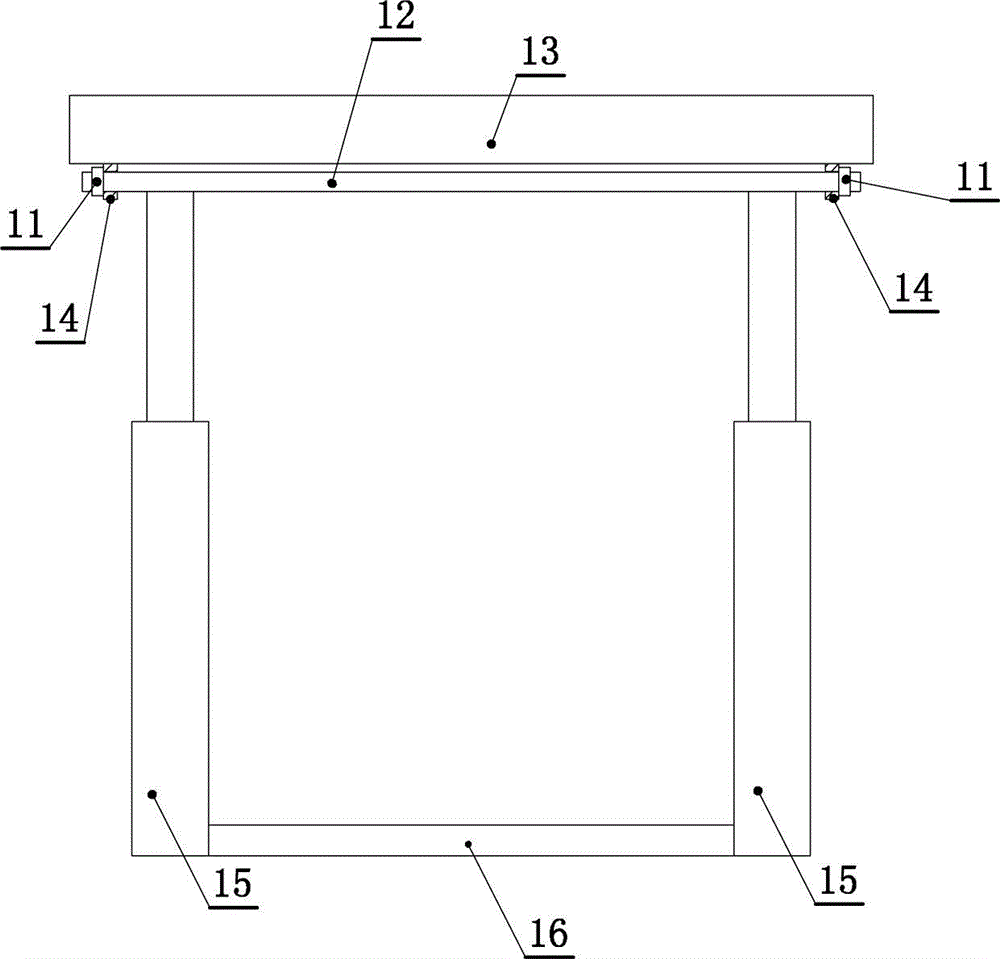
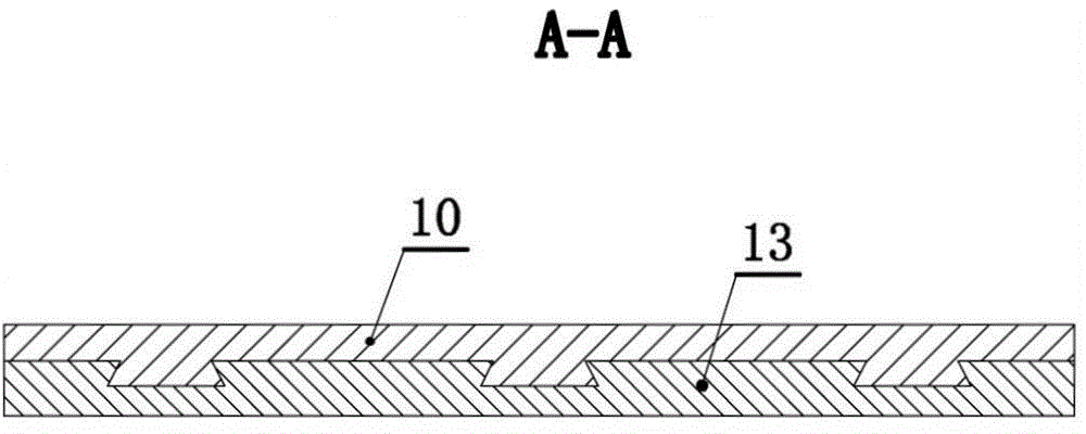
[0022] Such as figure 1 , figure 2 and image 3 As shown, a special-shaped cutting machine for special-shaped corners includes a support leg 17, the upper end of the support leg 17 is fixedly connected with a fixed table 9, and a long strip-shaped cutting port 8 is provided on the fixed table 9, and a motor 4 is fixedly installed under the fixed table 9. , Motor 4 transmission is connected with cutting disc 7, and cutting disc 7, the edge upper end of cutting disc 7 passes through cutting opening 8 to above fixed table top 9, and above structure just makes the present invention possess the function of common cutting.

[0023] The edge of the fixed table 9 outside the cutting opening 8 is hinged with a movable ta...


PUM


Abstract

The invention discloses a special cutter for a specially-shaped angle. A long-strip-shaped cutting hole is formed in a fixed table board; a motor is fixedly mounted below the fixed table board; the motor is in transmission connection with a cutting plate; the upper end of the side edge of the cutting plate goes through to a position above the fixed table board through the cutting hole; the side edge of the fixed table board outside the cutting hole is hinged with a movable table board; a connecting line for the movable table board and the fixed table board is parallel to the cutting plate; connecting points of the movable table board and the fixed table board are positioned at the lower ends of the movable table board and the fixed table board; the lower surface of the movable table board is fixedly connected with a long-strip-shaped slide slot; a connecting line for the movable table board and the fixed table board is mutually perpendicular to the slide slot; an inclined positioning rod is connected in the slide slot in a left-right sliding mode; an inclined positioning nut is in threaded connection on the inclined positioning rod; the inclined positioning rod is fixedly connected with the inclined positioning nut through the slide slot; and the inclined positioning rod is fixedly connected with a telescopic column integrally. The telescopic column comprises a sleeve; a stand column is movably spliced in the sleeve up and down; and the upper end of the stand column is fixedly connected with the inclined positioning rod integrally.

Description

technical field [0001] The invention relates to a cutting machine, in particular to a special-shaped cutting machine. Background technique [0002] Cutting machine is a kind of equipment used to cut hard materials, including stone and ceramic tiles, etc. This type of equipment is mostly used in building decoration. For the corners of the walls and pillars of the building, in order to decorate beautifully, it is necessary to chamfer the stones and tiles at the corners (see Figure 4 ), the current cutting machine can conveniently cut stones and tiles into regular squares. If chamfering stones or tiles is cut, it needs to be operated by hand. During the cutting process, it is completely controlled by the worker's feeling, so the cutting edge The corner effect is not good, and it is also inconvenient to operate, which is very tiring. Contents of the invention [0003] The invention aims at the deficiencies, and provides a special-shaped cutting machine for special-shaped cor...

Claims


Application Information

Patent Timeline
IPC IPC(8): B28D1/24B28D7/00
CPCB28D1/24B28D7/00B28D7/04B28D7/043
Inventor 付瑞兰
Owner 江苏三达利建材科技有限公司
Why Eureka
Try Eureka