Processing cutting tool

A technology for machining tools and cutting, which is used in wood processing appliances, manufacturing tools, rotary cutting tools, etc. It can solve the problem that the compromise solution is not always satisfactory, and achieve good cutting results, prolong service life, and reduce tool heads. The effect of prolonging the service life

Inactive Publication Date: 2012-08-08
LEDERMANN
View PDF5 Cites 3 Cited by
  • Summary
  • Abstract
  • Description
  • Claims
  • Application Information

AI Technical Summary

Problems solved by technology

A middle ground is to be chosen between the above two opposing trends, and as a result, the middle ground is not always satisfactory

Method used


Image

  • Processing cutting tool
  • Processing cutting tool
  • Processing cutting tool

Examples


Embodiment Construction

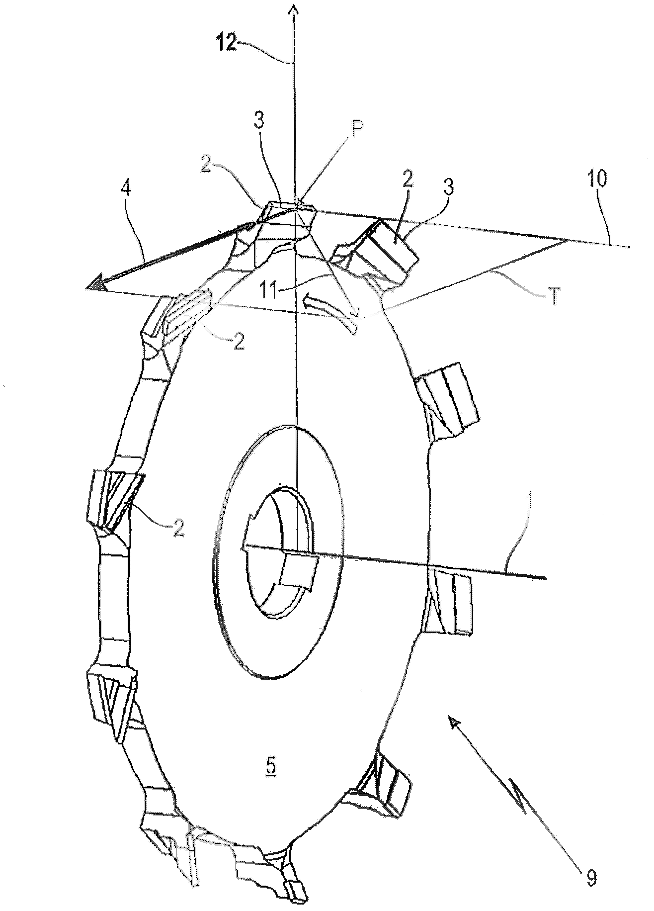
[0027] figure 1 An exemplary embodiment of a machining tool 9 according to the invention for material removal is shown in a perspective view, here the illustrated embodiment is provided for cutting wood or wooden materials. However, embodiments for any other material like especially metal, plastic and / or composite materials may also be suitable.

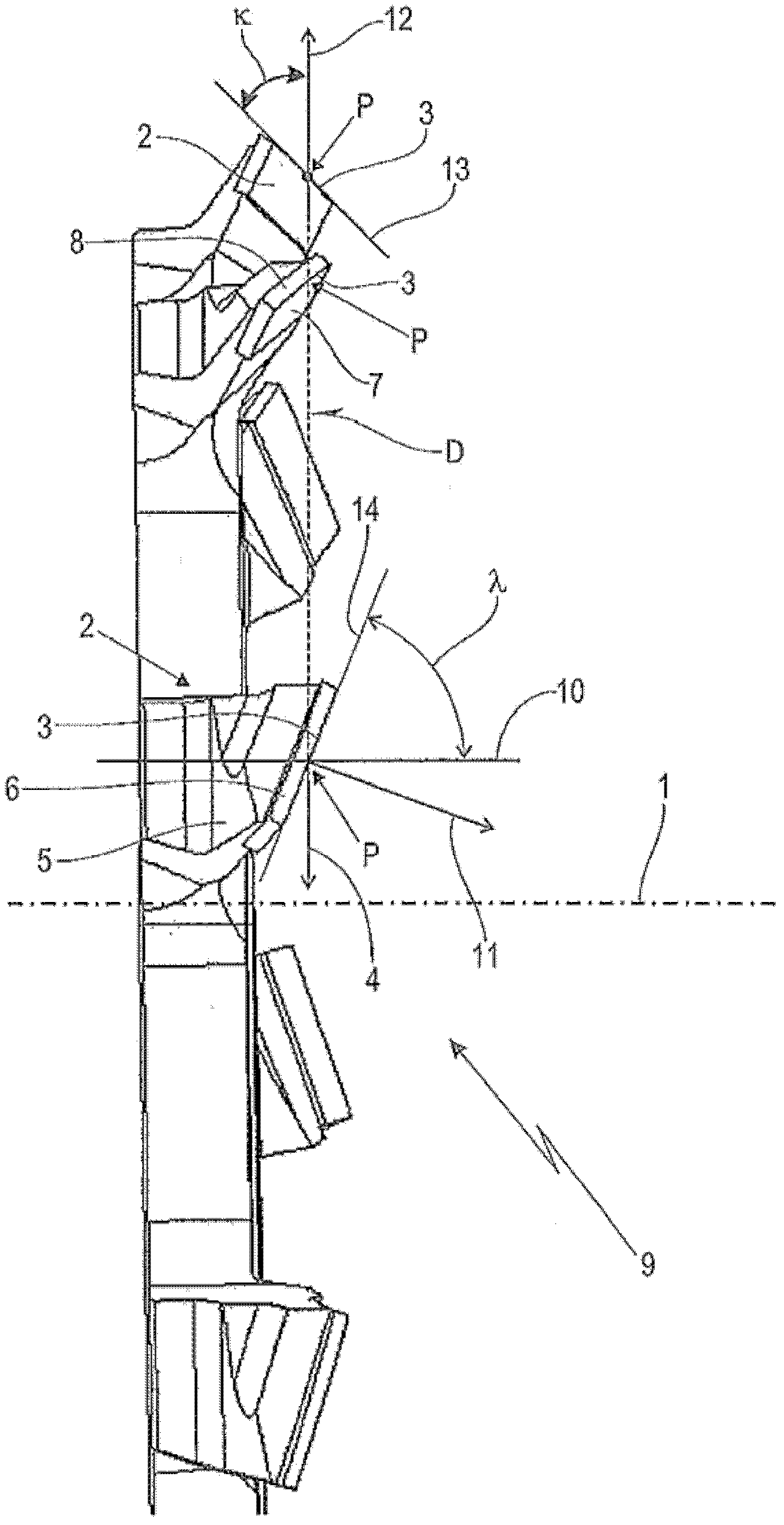
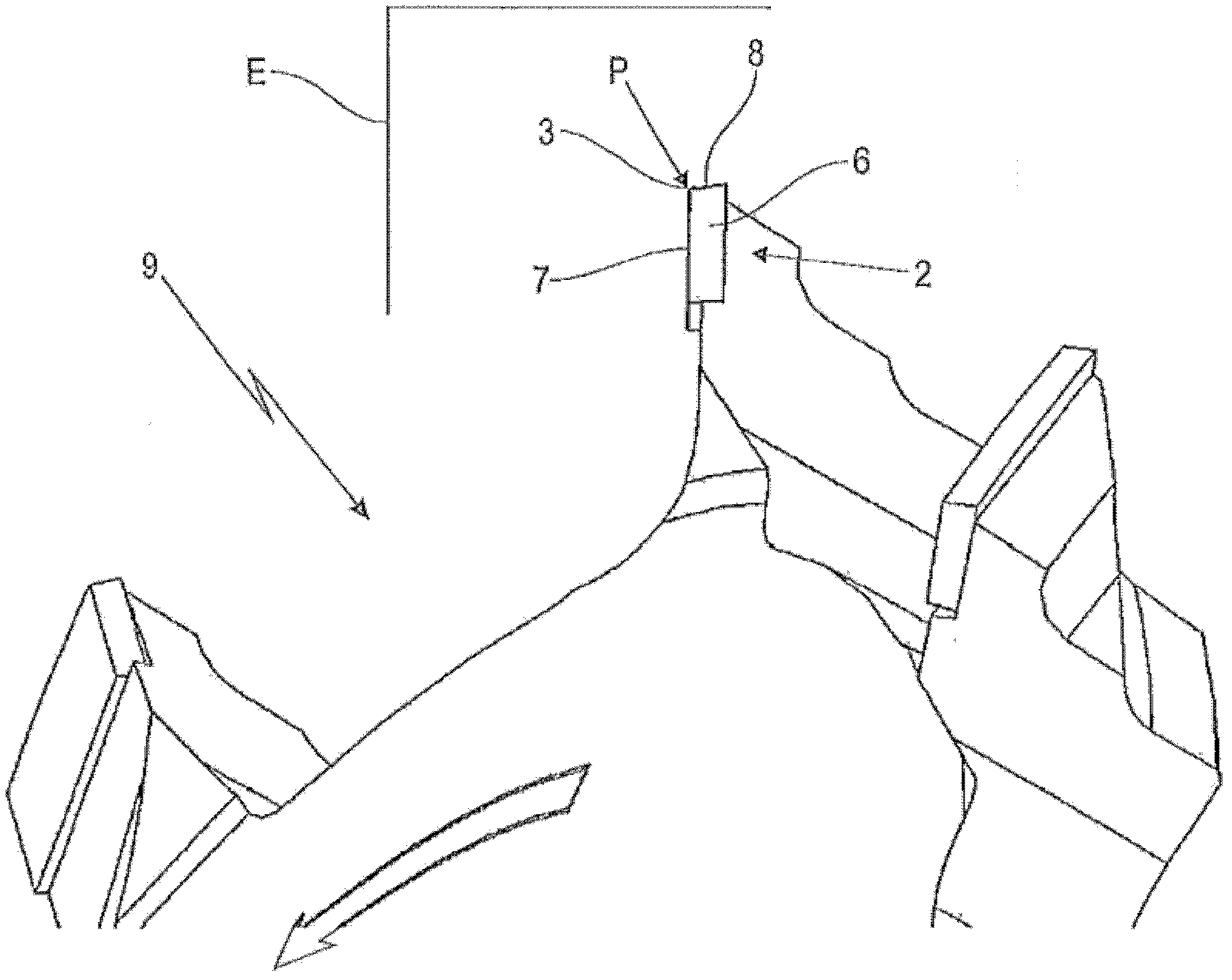
[0028] The machining tool 9 is provided for being driven in rotation about an axis of rotation 1 and for this purpose has a disk-shaped main body 5 , in the peripheral region of which a plurality of cutting heads 2 each having a cutting edge 3 are arranged. At least one cutter head is provided. In the illustrated embodiment, ten cutter heads 2 are evenly distributed around the body 5 .

[0029]Along each individual cutting edge 3 any point P can be chosen as a reference point. Starting from the axis of rotation 1 , a radial direction 12 passes through each point P of the cutting edge 3 . Due to the rotational movement of the mach...


PUM


Abstract

The invention refers to a Processing cutting tool (9) use for cutting and processing materials. The processing cutting tool is configured to be driven around a rotation axis (1) and has several cutting heads (2) with cutting edges (3) and at least one point (P) on the cutting edges (3). The cutting edges (3) are rotated about the rotation axis (1) to describe a cutting edge outline (13) circling the rotation axis (1). A rotation plane (D) is provided which comprises the at least one point (P) and is perpendicular to the rotation axis (1). A cross-section (E) of the cutting heads (2)are also provided which comprises the at least one point (P) and is perpendicular to the cutting edges (3). The cutting edges (3) form a crossed axis angle (lambda) relative to the rotation axis (1) on the at least one point (P). The cutting edge outline (13) form a tool cutting edge angle (kappa) relative to the rotation plane (D) at the at least one point (P). The cutting edges (3) at the point (P) and in the rotation plane (D) has an effective clearance angle (alpha eff), effective wedge angle (beta eff) and effective rake angle (gamma eff). The clearance angle (alpha eff) is no greater than zero DEG; the crossed axis angle (lambda) and the tool cutting edge angle (kappa) are coordinated such that effective clearance angle (alpha eff) is equal to or greater than zero DEG.

Description

technical field [0001] The invention relates to machining tools for the cutting machining of materials, especially wood or wood-based materials, metals, plastics and / or composite materials. Background technique [0002] Machining tools for material removal machining have a limited service life limited by the edge condition of their cutting tips. An important factor affecting service life is the wedge angle of the cutting edge. The largest possible wedge angle prolongs the service life and results in a better resistance to sharpness damage and chipping of the bit. [0003] However, an arbitrary wedge angle cannot be selected because the wedge angle is limited by other influencing factors. Many materials cannot or can only be machined poorly with small rake angles. For wood and timber, too small a rake angle leads to poor surface quality, so a sufficiently large positive rake angle must be chosen. [0004] According to the prior art, the relief angle is also designed to ha...

Claims


Application Information

Patent Timeline
Patent Type & Authority Applications(China)
IPC IPC(8): B23B27/08B23B27/14B23C5/08
CPCB23C2210/0407B23C2210/0428B23C5/06B27G13/08B23C2210/084B23C5/18B23C5/08
Inventor M·德雷斯勒
Owner LEDERMANN
Why Eureka
Try Eureka