Table type centrifugal machine

A centrifuge and desktop technology, applied in the direction of centrifuges, etc., can solve the problems of inconvenient operation process, achieve the effect of easy and convenient operation process, easy and convenient use process, and improve the convenience of operation

Pending Publication Date: 2022-05-31
CHINEO MEDICAL TECH CO LTD
View PDF1 Cites 0 Cited by
  • Summary
  • Abstract
  • Description
  • Claims
  • Application Information

AI Technical Summary

Problems solved by technology

[0004] When the desktop centrifuge in the related art is working, because the rotor body is a conical ring, when installing and taking the test tubes, it is necess

Method used


Image

  • Table type centrifugal machine
  • Table type centrifugal machine
  • Table type centrifugal machine

Examples


Embodiment Construction

[0034] The following is attached Figure 1-4 The application is described in further detail.

[0035] The embodiment of the present application discloses a desktop centrifuge.

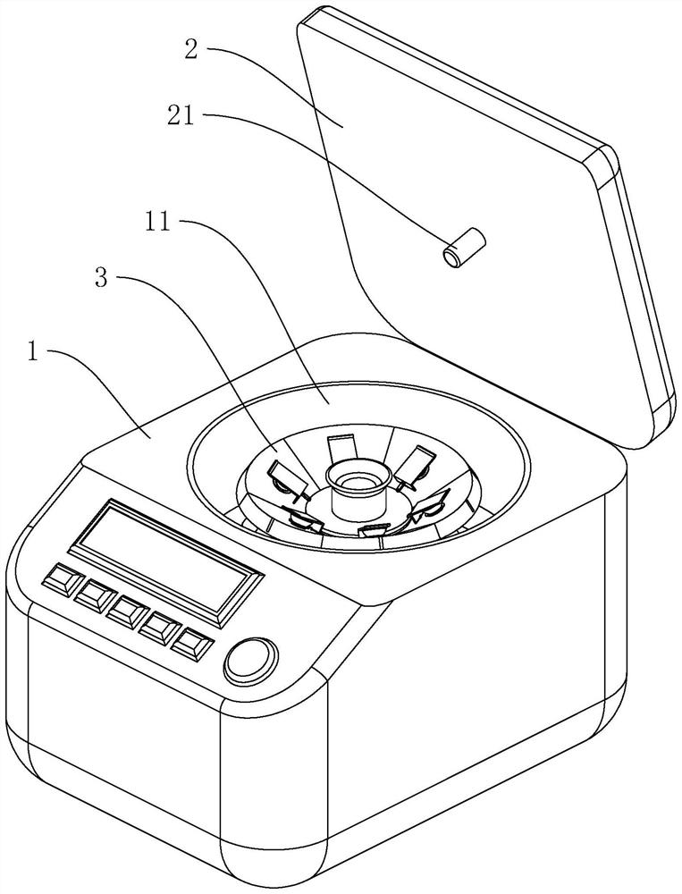
[0036] refer to figure 1 , figure 2 , the desktop centrifuge includes a body 1 , a cover plate 2 and a rotor body 3 . The body 1 is provided with a centrifugal chamber 11 , the centrifugal chamber 11 runs through the upper surface of the body 1 , and the cover plate 2 is hingedly arranged on the body 1 and is used to cover the centrifugal chamber 11 .

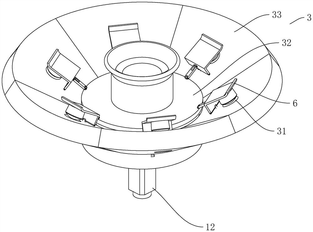
[0037] refer to figure 1 , figure 2 , the rotor body 3 is located in the centrifugal chamber 11, the central axis of the rotor body 3 is arranged in line with the central axis of the centrifugal chamber 11, and the motor 12 for controlling the rotation of the rotor body 3 is arranged in the centrifugal chamber 11. There is also a circle of test holes 31 distributed on the rotor body 3 , the upper ends of the test holes 31 are close to each other...


PUM


Abstract

The invention relates to a table centrifuge, and relates to the technical field of test instruments.The table centrifuge comprises a machine body, a cover plate and a rotor body, a centrifugal chamber is arranged in the machine body, the rotor body is located in the centrifugal chamber, the rotor body comprises a bottom plate and a plurality of supporting plates, and the supporting plates are distributed on the periphery of the bottom plate and connected to the bottom plate in an up-down rotating mode; test holes for insertion of test tubes are formed in the supporting plates in a penetrating manner, and a driving mechanism for controlling the supporting plates to rotate synchronously is arranged on the bottom plate. By arranging the turnover type supporting plate, synchronous mounting and taking of multiple test tubes are achieved at a time, so that the operation process is easier and more convenient, and the operation convenience is improved.

Description

technical field [0001] The application relates to the field of test instruments, in particular to a desktop centrifuge. Background technique [0002] A centrifuge is a machine that uses centrifugal force to separate components in a mixture of liquid and solid particles or liquid and liquid. The centrifuge is mainly used to separate the solid particles in the suspension from the liquid, or to separate two different densities and immiscible liquids in the emulsion. [0003] Chinese patent CN206996870U discloses a micro desktop centrifuge, which includes a chassis body and a door cover. A centrifugal chamber is arranged in the chassis body. A central shaft is arranged in the center of the centrifugal chamber. A supporting plate is fixed on the central shaft, and the top of the central shaft above the supporting plate is Multiple sets of centrifuge tube holders are installed, a rotor body is arranged in the centrifuge chamber, the rotor body is a conical ring, and a plurality o...

Claims


Application Information

Patent Timeline
IPC IPC(8): B04B5/02B04B7/00B04B7/02
CPCB04B5/02B04B7/00B04B7/02
Inventor 谷为岳裴波牟晓宁
Owner CHINEO MEDICAL TECH CO LTD
Why Eureka
Try Eureka