Lifting and placing machine for rubber and plastic pipes

A technology of rubber-plastic tube and hoisting mechanism, which is applied in cranes, trolley cranes, transportation and packaging, etc., can solve problems such as length limitation of rubber tubes and difficult control of rubber tubes.

Inactive Publication Date: 2016-01-20
开原起重机有限公司
View PDF7 Cites 0 Cited by
  • Summary
  • Abstract
  • Description
  • Claims
  • Application Information

AI Technical Summary

Problems solved by technology

[0002] In the known technical field, in the manufacturing plant of large-scale rubber tubes, it is generally necessary to lift them by cranes, but it

Method used


Image

  • Lifting and placing machine for rubber and plastic pipes
  • Lifting and placing machine for rubber and plastic pipes

Examples


Embodiment Construction

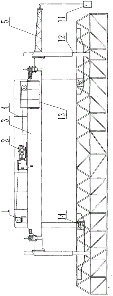
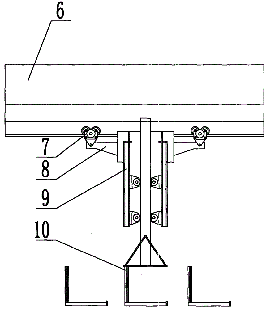
[0011] The present invention is described in further detail now in conjunction with accompanying drawing. These drawings are all simplified schematic diagrams, which only illustrate the basic structure of the present invention in a schematic manner, so they only show the configurations related to the present invention.

[0012] Such as figure 1 and figure 2 The preferred embodiment of the rubber and plastic pipe lifting and placing machine of the present invention shown has a main beam 3, a lifting mechanism 2 is installed in the middle of the main beam 3, and a connecting lifting mechanism 2 is respectively installed at both ends of the main beam 3 The lifting pulley 1 is provided with a railing 4 above the main beam 3, and a cart traveling beam 6 is provided above the main beam 3, and the cart traveling beam 6 is hoisted respectively by two symmetrically arranged carts 7. There are end beams 8, and a swing device 9 is arranged between the two end beams 8. The swing device...


PUM


Abstract

The invention relates to a lifting and placing machine for rubber and plastic pipes. A lifting mechanism is mounted in the middle of a main beam. Lifting pulleys connected with the lifting mechanism are mounted at the two ends of the main beam respectively. A large-vehicle walking beam is arranged on the upper side of the main beam. End beams are suspended on the large-vehicle walking beam through two symmetrically-arranged large-vehicle cranes respectively. A placing device is arranged between the two end beams. A lifting appliance is in sliding connection with the placing device through guide posts. An electrical support is fixed to one end beam and connected with an electrical console. A platform is arranged on the lower side of the main beam. The lower end of the platform is connected with the lifting appliance through lifting appliance pulley blocks. The lifting and placing machine is mainly applied to carrying and placing of soft, thin and long objects such as the rubber pipes and the plastic pipes, and the problems that the soft, thin and long objects made of rubber, plastic and the like can only be carried manually and it is difficult to deliver the goods out of warehouses, put the goods in the warehouses and load trucks with the goods are mainly solved. According to the scheme, the lifting and placing machine can be used for carrying the goods, placing the goods on goods racks in the warehouses, fetching the goods and loading the trucks with the goods.

Description

technical field [0001] The invention relates to a machine for lifting and placing rubber and plastic pipes. Background technique [0002] In the known technical field, in the manufacturing plant of large-scale rubber tubes, it is generally necessary to lift them by cranes, but it is difficult for traditional lifting devices to control the rubber tubes well, and the length of the rubber tubes that can be hoisted is also limited . Contents of the invention [0003] The technical problem to be solved by the present invention is: to overcome the above problems, to provide a rubber and plastic tube lifting and placing machine, which can hoist the rubber tube with a long length. [0004] The technical solution adopted by the present invention to solve the technical problem is: a rubber and plastic pipe lifting and placing machine, which has a main beam, a lifting mechanism is installed in the middle of the main beam, and a lifting mechanism is installed at both ends of the main...

Claims


Application Information

Patent Timeline
IPC IPC(8): B66C19/00
Inventor 孟津竹李国松李继松战贺齐鹏
Owner 开原起重机有限公司
Why Eureka
Try Eureka