Slag discharging mechanism of shield tunneling machine and muddy water balance shield tunneling machine

A technology of shield machine and mud discharge pipe, applied in mining equipment, earthwork drilling, tunnels, etc., can solve the problems of slow construction progress, high equipment maintenance cost, affecting the stability of slag carrying, and reduce load and pipeline wear. , The effect of improving mud circulation capacity and reducing equipment maintenance costs

Active Publication Date: 2016-01-20
RAILWAY CONSTR HEAVY IND XINJIANG CO LTD +1
View PDF7 Cites 29 Cited by
  • Summary
  • Abstract
  • Description
  • Claims
  • Application Information

AI Technical Summary

Problems solved by technology

[0003] For the geology of water-rich and large-size pebble-sand interbedded strata represented by Lanzhou and Chengdu, due to the large amount of pebbles and large particle size (the maximum particle size can reach 500mm), the existing mud-water balance shield machine is broken when the gravel is broken. , pipeline slag carrying and other aspects can not achieve satisfactory results
Specifically, due to the limited crushing capacity of the existing mud-water balance shield machine, the amount of muck entering the soil bin of the shield machine within a unit time cannot be too much, and the advancement speed of the shield machine is limited, resulting in low construction efficiency of the shield machine. The construction progress is slow; and the gravel produced by the crushing of large-sized pebbles will cause wear and tear on the sludge discharge pump and the mud-water circulation pipeline, and the equipment maintenance cost is high. At the same time, pipeline deposition will impact the mud system and affect the stability of slag carrying
It can be seen that the existing mud-water shield machine cannot be applied on a large scale in the geology of water-rich and large-size pebble-sand interbedded formations

Method used


Image

  • Slag discharging mechanism of shield tunneling machine and muddy water balance shield tunneling machine
  • Slag discharging mechanism of shield tunneling machine and muddy water balance shield tunneling machine
  • Slag discharging mechanism of shield tunneling machine and muddy water balance shield tunneling machine

Examples


Embodiment Construction

[0029] The present invention will be further described in detail below in conjunction with the accompanying drawings and specific embodiments.

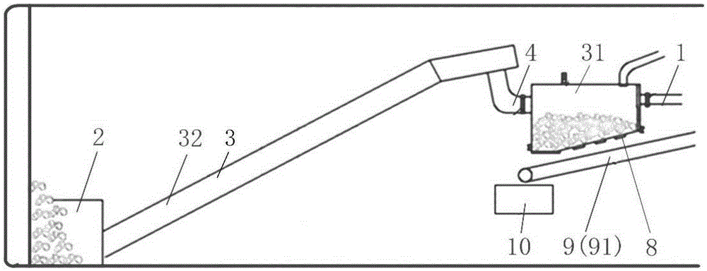
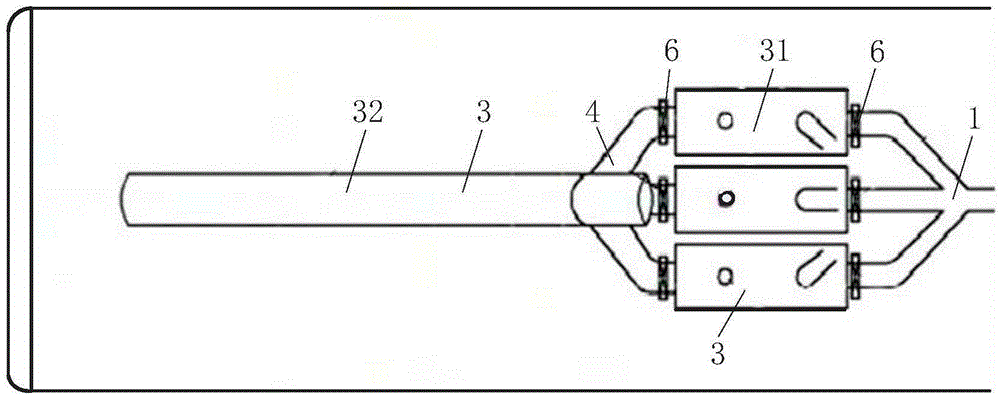
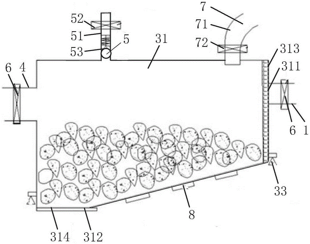
[0030] Such as Figure 1 to Figure 3 As shown, the slag discharge mechanism of the shield machine in this embodiment includes a mud discharge pipeline 1 and a soil bin 2. The soil bin 2 is used to temporarily store the muck cut from the cutter head of the shield machine. A separation device 3 is provided between the mud discharge pipelines 1. The separation device 3 is used to separate the mud and gravel in the muck. The soil bin 2 is connected with the input end of the separation device 3. The pipeline 1 communicates, and the gravel output end of the separation device 3 is provided with a gravel discharge device 9 . In the present invention, a separation device 3 is provided between the soil bin 2 and the mud discharge pipeline 1. At this time, the mud mixed with gravel is directly transported to the separation device 3 through the ...


PUM


Abstract

The invention discloses a muddy water balance shield tunneling machine and a slag discharging mechanism thereof. The slag discharging mechanism comprises a mud discharging pipeline and a soil bin for storing residue soil; a separating device for separating mud in the residue soil from gravels is arranged between the soil bin and the mud discharging pipeline; the soil bin communicates with a feeding end of the separating device; a mud discharging end of the separating device communicates with the mud discharging pipeline; and a gravel discharging end of the separating device is provided with a gravel discharging device. The muddy water balance shield tunneling machine comprises a shield and the slag discharging mechanism which is arranged in the shield. The slag discharging mechanism has the advantages that safety and stability of a slag outlet system of the muddy water balance shield tunneling machine are improved, and construction efficiency is also improved.

Description

technical field [0001] The invention relates to the technical field of shield machines, in particular to a slag discharge mechanism of a shield machine and a mud-water balance shield machine. Background technique [0002] The existing mud-water shield construction needs to crush large-sized pebbles into gravels below 100mm, pass through the grid and enter the mud discharge pipe, and complete the muck transportation through the mud discharge pipe. [0003] For the geology of water-rich and large-size pebble-sand interbedded strata represented by Lanzhou and Chengdu, due to the large amount of pebbles and large particle size (the maximum particle size can reach 500mm), the existing mud-water balance shield machine is broken when the gravel is broken. , pipeline slag carrying and other aspects can not achieve satisfactory results. Specifically, due to the limited crushing capacity of the existing mud-water balance shield machine, the amount of muck entering the soil bin of the...

Claims


Application Information

Patent Timeline
Patent Type & Authority Applications(China)
IPC IPC(8): E21D9/08E21D9/12
Inventor 刘飞香程永亮刘海华麻成标徐震
Owner RAILWAY CONSTR HEAVY IND XINJIANG CO LTD
Why Eureka
Try Eureka