Movable valve seat type throttling valve

A technology of throttle valve and moving valve seat, which is applied in the direction of lifting valve, valve device, engine components, etc., can solve problems such as cavitation wear, valve self-excited vibration, pressure drop, etc., to reduce the hazards of cavitation and leakage, The effect of prolonging the service life and increasing the stability

Inactive Publication Date: 2016-01-20
OCEAN UNIV OF CHINA
View PDF8 Cites 4 Cited by
  • Summary
  • Abstract
  • Description
  • Claims
  • Application Information

AI Technical Summary

Problems solved by technology

[0003] (1) The valve core moves relative to the valve seat. The valve core is generally conical or spherical. When the fluid passes through the valve port, hydraulic power will be generated, causing the self-excited vibration of the valve, which will affect the stability and reliability of the entire system.
[0004] (2) The liquid pressure entering from the inlet directly acts on the valve core to generate axial thrust. Although part of the axial force can be balanced by changing the structure of the valve core, it cannot be completely balanced, and zero-torque adjustment of the manual handle cannot be achieved.
[0005] (3) For the transmission and control systems of some low-viscosity working media (such as water, including seawater, fresh water or high water base, etc.), due to the physical and chemical characteristics of the working medium, at the valve port, the flow rate is high, wire drawing erosion occurs, and the pressure will drop sharply , resulting in severe cavitation, resulting in cavitation wear
Traditional single-stage throttle valves cannot overcome this problem

Method used


Image

  • Movable valve seat type throttling valve

Examples


Embodiment 1

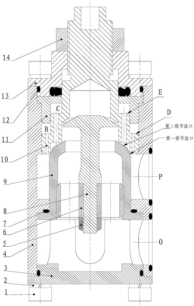
[0024] Example 1, such as figure 1 As shown, this embodiment discloses a moving valve seat type throttle valve. The throttle valve includes a valve body 4 with a cavity. The front end cover 13 and the rear end cover 3 are all connected with the valve body 4 by screws 1 The valve body 4 is fixedly connected with the spring washer 2, and the valve body 4 has a water inlet P and a water outlet O communicating with the above-mentioned cavity; the cavity of the valve body 4 is provided with a valve core 9 and a valve seat 10, wherein the valve core 9 passes through the back end cover 3 is fixed in the cavity inside the valve body, the valve seat 10 is embedded in the cavity inside the sleeve 11 and the valve body 4, the upper end of the valve seat 10 extends out of the axial through hole of the front end cover 13, the sleeve 11 and the front end cover 13 and the valve body 4 are press-fitted. The valve seat 4 includes two stepped structures D and E. The rising end of the stepped str...


PUM


Abstract

The invention discloses a movable valve seat type throttling valve. The throttling valve comprises a valve body with a cavity. A front end cover and a rear end cover are both fixedly connected with the valve body. The valve body is provided with a water inlet and a water outlet which are communicated with the cavity. A valve element and a valve seat are arranged in the cavity of the valve body, and the valve element is fixed into the cavity in the valve body through the rear end cover. The valve seat is embedded in a sleeve and the cavity in the valve body. The upper end of the valve seat stretches out of an axial through hole of the front end cover. The sleeve is in force fit with the front end cover and the valve body. The valve seat comprises a two-step structure, and the two steps have the same superficial area. According to the throttling valve, through the center rod structure of the valve element and the structure that two step surfaces have the same area, the function of compensating hydrodynamic force of fluid can be achieved, impact force and erosion to the valve seat are reduced, and the stability of manual adjustment of the valve seat is improved.

Description

Technical field [0001] The invention relates to the field of flow control elements, in particular to a throttle valve suitable for fluid transmission and control systems in this field. Background technique [0002] Throttle valve, as a commonly used flow control element in fluid transmission and control systems, is mainly used to control the movement speed of the actuator. However, in the transmission throttle: [0003] (1) The valve core moves relative to the valve seat. The valve core is generally conical or spherical. When fluid passes through the valve port, hydraulic power will be generated, which will cause self-excited vibration of the valve, which will affect the stability and reliability of the entire system. [0004] (2) The liquid pressure entering from the inlet directly acts on the spool to generate axial thrust. Although part of the axial force can be balanced by changing the spool structure, it cannot be completely balanced and the manual handle for zero torque adjust...

Claims


Application Information

Patent Timeline
Patent Type & Authority Applications(China)
IPC IPC(8): F16K1/36F16K1/42F16K1/32
CPCF16K1/36F16K1/32F16K1/42
Inventor 杨友胜吴进军聂松林刘贵杰冯辅周王帅朱永杰刘冬婷
Owner OCEAN UNIV OF CHINA
Why Eureka
Try Eureka