
Rock shearing fracture surface boundary depicting device and method

A technology of shear failure and delineation device, applied in the field of geotechnical engineering, can solve problems such as inconvenient operation and large error, and achieve the effect of solving excessive human error, reducing operation error and realizing programmed delineation.

Active Publication Date: 2016-01-20
CHINA THREE GORGES UNIV
View PDF6 Cites 3 Cited by
  • Summary
  • Abstract
  • Description
  • Claims
  • Application Information

AI Technical Summary

Problems solved by technology

Since the shear failure surface is an uneven and irregular shape, the influence of factors such as the color difference between the transparent paper and the rock sample, the fixation of the drawing paper, the drawing angle and the shooting angle of the photo, these two methods are not effective in describing the effective shear surface. There are large errors all the time, and the operation is inconvenient

Method used


Image

  • Rock shearing fracture surface boundary depicting device and method
  • Rock shearing fracture surface boundary depicting device and method
  • Rock shearing fracture surface boundary depicting device and method

Examples


Embodiment Construction

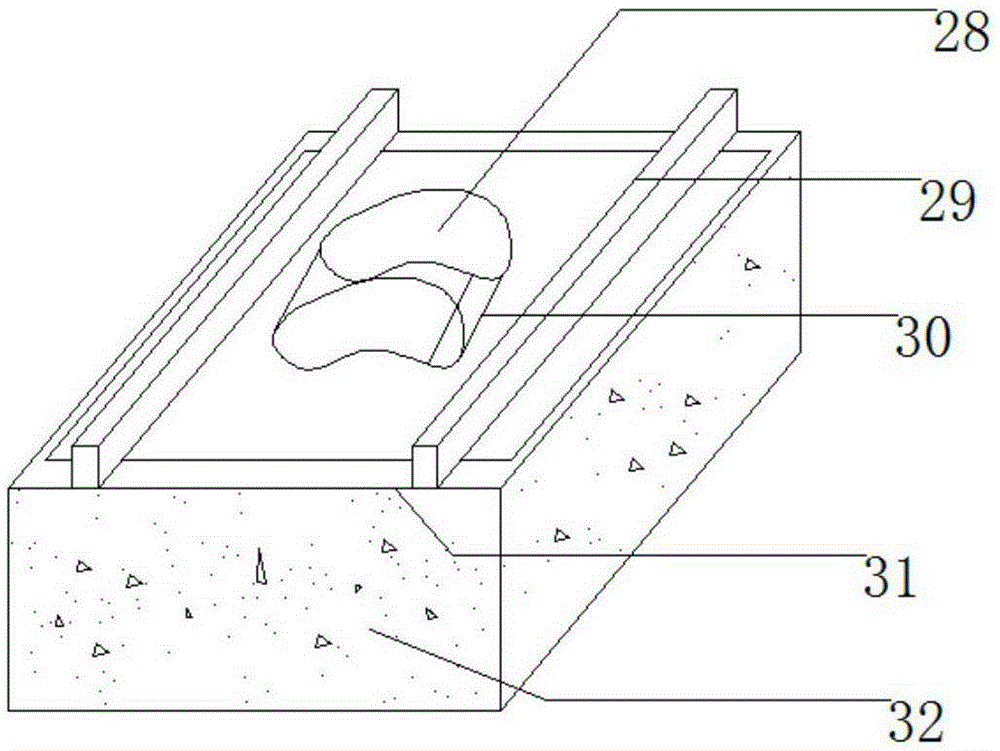
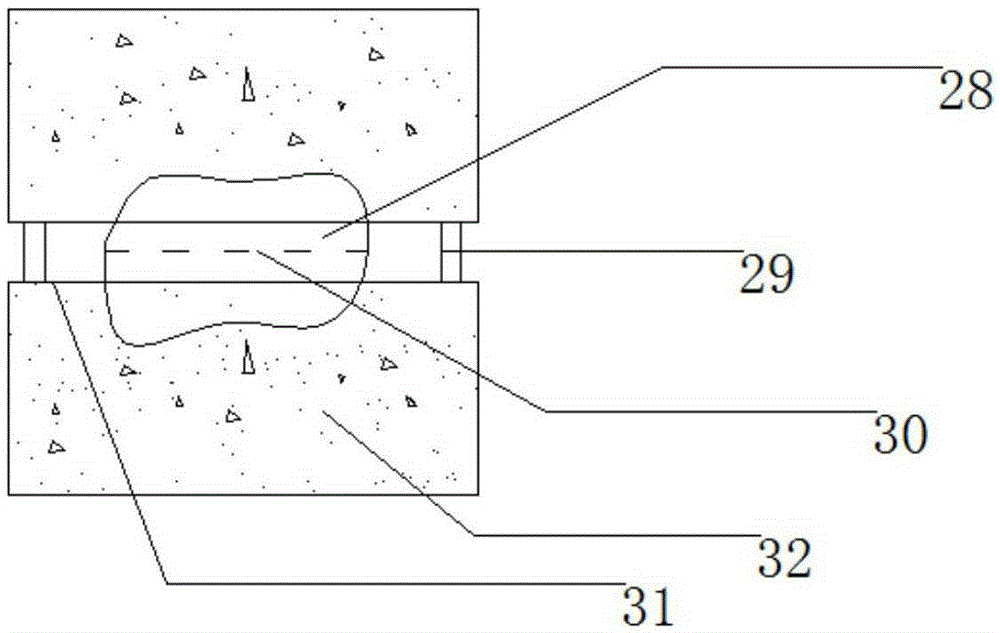
[0034] Such as Figure 4~Figure 10 As shown, a rock shear failure surface boundary delineation device includes a support cylinder 1, a rotating sleeve 3, and a support 7. The support cylinder 1 is installed on the support 7, and the bottom of the operating platform 14 is connected to the support 7. The rock sample 28 is located on the operating platform 14 .

[0035] The middle part of the rotating sleeve 3 is fixedly connected with a vertical rod. The vertical rod is inserted into the bearing 12 installed in the supporting cylinder 1. The upper part of the supporting cylinder 1 is equipped with a rotating bearing 10. One end of the oblique rod 2 is connected to the rotating bearing 10. The other end of the rod 2 is connected to the rotating sleeve 3, and the horizontal linkage rod 15 is movably installed inside the rotating sleeve 3 through rollers 9 arranged symmetrically up and down.

[0036] The drawing probe body 17 is connected to the left end of the horizontal linkage ...


PUM


Abstract

A rock shearing fracture surface boundary depicting device and a method are disclosed. A support cylinder, a rotation sleeve and a support seat are included. The support cylinder is installed on the support seat. An operation platform bottom is connected to the support seat. A rock sample is located on an operation platform. A center section of the rotation sleeve is fixedly connected to a vertical rod. The vertical rod is inserted into and is installed on a bearing in the support cylinder. An upper portion of the support cylinder is provided with a rotation bearing. One end of a diagonal rod is connected to the rotation bearing. The other end of the diagonal rod is connected to the rotation sleeve. A horizontal interlocking bar is movably installed in an internal portion of the rotation sleeve. A depicting probe body is connected to a left end of the horizontal interlocking bar. A rotation handle is connected to the rotation bearing of the depicting probe body. An outer cylinder of a paintbrush is connected to a right end of the horizontal interlocking bar. An electronic paintbrush is inserted into the outer cylinder of the paintbrush and is fixed through a rotary knob. An electronic drawing board is arranged below the electronic paintbrush. The electronic drawing board is connected to a computer. By using the device and the method, problems that a personal error of rock shearing surface area calculation is large, operation is difficult and so on can be solved; and procedural depicting of a rock shearing fracture surface is realized.

Description

technical field [0001] The invention relates to the field of geotechnical engineering, in particular to a device and method for delineating the boundary of a rock shear failure surface. Background technique [0002] Rock mechanics test is the basis of rock mechanics and one of the important means to study rock mechanics and engineering. Although scientific calculation and theoretical analysis have reached a considerable height, rock mechanics tests still play an irreplaceable role in directly solving mechanical problems in practical engineering. With the rapid development of modern rock mechanics theory, test instruments for testing various rock mechanics parameters have emerged as the times require. Although there are many types of rock mechanics test instruments, they can meet the test requirements of various rock mechanics parameters. [0003] Among them, the direct shear test is a commonly used method for testing the shear strength of rocks and jointed surfaces. The sta...

Claims


Application Information

Patent Timeline
IPC IPC(8): G01B21/28
Inventor 邓华锋占宽葛振凌雷涛占世源方景成肖瑶张恒宾王晨玺杰李春波常德龙
Owner CHINA THREE GORGES UNIV
Learn More