Casing axial load testing device during the period for waiting on cement mortar setting

A technology of axial load and test device, applied in the direction of measuring device, measuring force, instrument, etc., can solve problems such as the difference between the force of the test casing and the actual working condition

Active Publication Date: 2016-01-20
NORTHEAST GASOLINEEUM UNIV
View PDF7 Cites 13 Cited by
  • Summary
  • Abstract
  • Description
  • Claims
  • Application Information

AI Technical Summary

Problems solved by technology

[0003] The purpose of the present invention is to provide a casing axial load test device during the cement slurry waiting period, which is used to solve the problem of the stress and actual situation of the indoor laboratory test casing in the prior art. The problem of different working conditions

Method used


Image

  • Casing axial load testing device during the period for waiting on cement mortar setting
  • Casing axial load testing device during the period for waiting on cement mortar setting
  • Casing axial load testing device during the period for waiting on cement mortar setting

Examples


Embodiment Construction

[0022] Below in conjunction with accompanying drawing, the present invention will be further described:

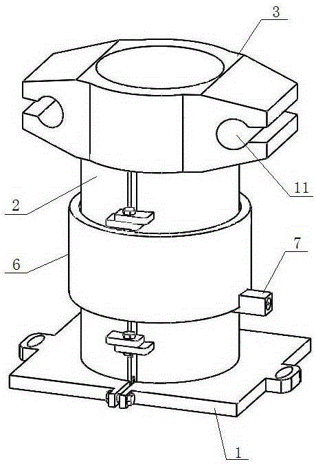
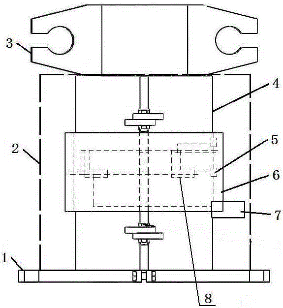
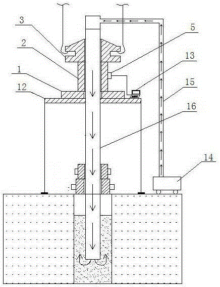
[0023] Such as figure 1 , figure 2 As shown, the casing axial load test device during the cement slurry waiting period includes a lower base 1, a sensor 2, and an upper elevator 3. The lower base 1 is fixed on the drilling platform 12, the sensor 2 is fixed on the lower base 1, and the upper elevator 3 sits on the sensor 2, and forms a casing channel through the three; the lower base 1 is installed on the drilling platform 12 during the test, and mainly plays the role of fixing the sensor 2, such as Figure 4 As shown, the lower base 1 is composed of two halves combined together. The inner side of each half has a semi-circular groove, and the outer side of each half is provided with mounting holes. After the two halves are combined, an annular fixing groove is formed. 9 and the central hole 10, the sensor 2 is seated in the fixing groove 9 and fastened by two halves; th...


PUM


Abstract

The present invention relates to a casing axial load testing device during the period for waiting on cement mortar setting. The casing axial load testing device during the period for waiting on cement mortar setting includes a bottom base, a sensor and an upper elevator. The bottom base is fixed on a drilling platform, the sensor is fixed on the bottom base, the upper elevator locates on the sensor, and a casing pipe channel running through the bottom base, the sensor, and the upper elevator is formed. The sensor is composed of a load-carrying elastomer, a testing circuit and an adapter. The load-carrying elastomer is a cylindrical body which is composed of two half cylinders by interlocking. A foil gage is arranged on the load-carrying elastomer, the foil gage bonds the load-carrying elastomer through an adhesive agent, and the testing circuit and the adapter are arranged outside the load-carrying elastomer. The casing axial load testing device during the period for waiting on cement mortar setting performs the on-site dynamic monitoring for casing axial loads during the period for waiting on cement mortar setting by aiming at various well depths and various cement mortar proportions, and the data is true and reliable.

Description

technical field [0001] The invention relates to a device for testing the casing of an oil field drilling facility, in particular to a device for testing the axial load of the casing during the cement slurry waiting period. Background technique [0002] Various complex physical and chemical changes will occur during the gelling process of the cement slurry, and the system will gradually form a space grid structure, and the slurry will form a certain strength connection with the casing wall and the well wall, and then there will be weightlessness. The gelation and weight loss of the cement slurry have a great influence on the internal stress of the casing string. As the cement solidifies, the stress and deformation of the casing string will also be consolidated in the cement sealing section, affecting its performance and becoming an important factor affecting the life of the casing. In order to understand the mechanism of cement slurry weight loss and prevent gas channeling, ...

Claims


Application Information

Patent Timeline
Patent Type & Authority Applications(China)
IPC IPC(8): G01L1/22
Inventor 丁宇奇刘巨保邱枫周纪满黄金波张宇卢齐法
Owner NORTHEAST GASOLINEEUM UNIV
Why Eureka
Try Eureka