
Tool Wear Detector

A tool wear and detector technology, applied in the field of mechanical processing, can solve the problems of difficult position and angle of the tool to be tested, low data accuracy, etc., and achieve the effects of intuitive display, accurate collection, and novel structure

Active Publication Date: 2017-11-07
CHANGCHUN EQUIP TECH RES INST
View PDF8 Cites 0 Cited by
  • Summary
  • Abstract
  • Description
  • Claims
  • Application Information

AI Technical Summary

Problems solved by technology

[0003] The invention provides a tool wear detector to solve the problem that the position and angle of the tool to be tested are difficult to accurately control in the existing manual pushing and placing of the tool holder, adjustment of the position and direction, and adjustment of the height of the microscope lens. The problem of low data accuracy

Method used


Image

  • Tool Wear Detector
  • Tool Wear Detector
  • Tool Wear Detector

Examples


Embodiment Construction

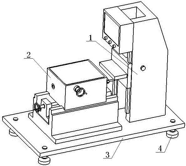
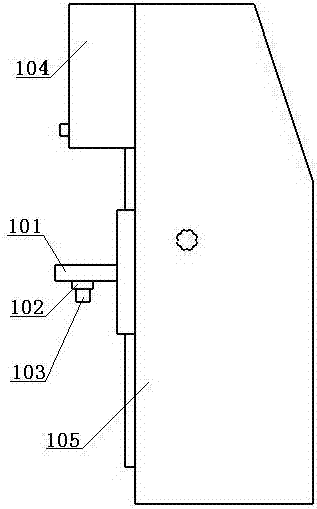
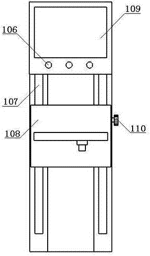
[0017] The lens height adjustment device 1 and the tool axial and rotation adjustment device 2 are fixedly connected with the support platform 3 respectively, and the platform adjustment screw 4 is screwed with the four corners of the bottom surface of the support platform 3; the lens 103 is installed under the lens support plate 101, and the lens is finely adjusted The knob 102 is installed on the outer edge of the lens 103, the guide rail one 107 is installed on the front portion of the casing 105, and the display system 104 is installed on the upper end of the front surface of the casing 105. The display system 104 has a display adjustment knob 106 and a liquid crystal screen 109, and the slide block 108 and Guide rail one 107 is slidingly connected, the rack support plate 112 is fixedly connected to the inside of the slider 108, the rack 113 is installed on the rack support plate 112, the two ends of the shaft of the worm 114 are respectively connected to the two side plates...


PUM


Abstract

The invention relates to a tool wear detector, which belongs to the field of mechanical processing. The lens height adjustment device and the tool axial and rotation adjustment device are respectively fixedly connected with the support platform, and the platform adjustment screws are connected with four corner threads on the bottom surface of the support platform. The invention has the advantages of novel structure, convenient tool movement adjustment and rotation adjustment, intuitive experimental data display, and more accurate collection of tool wear information.

Description

technical field [0001] The invention belongs to the field of mechanical processing, in particular to a tool detection device. Background technique [0002] The relationship between tool life and cutting speed, feed per tooth, and depth of cut needs to be determined through experiments. In order to verify the rationality of the selected tool material and cutting parameters, the durability experiments of different tool materials are carried out for difficult-to-machine materials. Under the given workpiece material, tool material and geometric properties, processing methods and processing equipment, the designed The tool wear measurement experiment was carried out under different cutting parameters, and the wear curve was drawn. Data analysis was carried out to obtain the relationship between tool durability and cutting parameters. In order to obtain experimental data more accurately, it is usually necessary to collect tool wear information under a microscope. The current met...

Claims


Application Information

Patent Timeline
Patent Type & Authority Patents(China)
IPC IPC(8): G01N21/84
Inventor 苗立琴姜合萍姜继春蒯晓俊张大舜于航王静徐向兰崔万瑞胡东吉
Owner CHANGCHUN EQUIP TECH RES INST
Learn More