

A Fault Location Measurement System and Method Based on Optical Current Transformer
A current transformer and fault location technology, which is applied in the direction of the fault location, can solve the problems of low precision, poor reliability of distance measurement, etc.
- Summary
- Abstract
- Description
- Claims
- Application Information
AI Technical Summary
Problems solved by technology
Method used
Image

Examples
Embodiment Construction
[0023] The present invention will be described below in conjunction with the accompanying drawings.
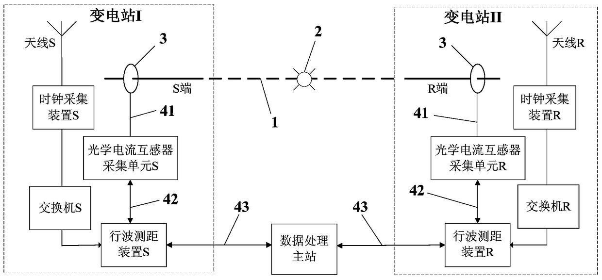
[0024] The present invention relates to a fault location system based on optical current transformers. A transmission line 1 is connected to a substation I and a substation II. The fault location system is used to measure the fault point 2 in the transmission line 1 between the two substations. location, whose structure is as figure 1 As shown, it includes optical current transformers, traveling wave ranging devices, switches and clock acquisition devices that are sequentially connected in the two substations (substation I and substation II), and also includes the data set between substation I and substation II Handle the master. The optical current transformers of the two substations all include the optical current transformer sensitive unit 3 and the optical current transformer acquisition unit connected to each other through the first optical cable 41, and the two optical ...
PUM
 Abstract
Description
Claims
Application Information