Testing device and method for defocused spot and color bias of optical system

An optical system and testing device technology, applied in the direction of testing optical performance, etc., can solve the problems of time-consuming and laborious adjustment process, large aiming error, low testing efficiency, etc., and achieve the effect of improving measurement accuracy, convenient real-time adjustment, and excellent imaging quality.

Inactive Publication Date: 2011-05-11
XI'AN INST OF OPTICS & FINE MECHANICS - CHINESE ACAD OF SCI
View PDF0 Cites 29 Cited by
  • Summary
  • Abstract
  • Description
  • Claims
  • Application Information

AI Technical Summary

Problems solved by technology

[0004] 1. Low measurement accuracy
Due to the use of human eyes for observation, what the human eyes see is only the distribution of geometric shapes, not the distribution of energy, which cannot truly reflect the distribution of diffuse spots in the measured optical system. At the same time, due to the differences between individuals, the aiming error is large. The measurement accuracy of the diffuse spot size is about 10 μm, which can only roughly determine the range of the color deviation value, but cannot accurately measure the color deviation value
[0005] 2. The installation and debugging work is complicated and the test efficiency is low
Since the optical bench uses a halogen tungsten light source, if you want to obtain a monochromatic wavelength of the diffuse spot, you must add an interference filter in front of the light source, which greatly reduces the received energy, and because the transmittance of different filters is different , resulting in uneven energy, it is not easy to find the best image plane that meets the measurement needs, and the adjustment process is time-consuming and laborious;
[0006] 3. Limited by the visual function of the human eye, the spectral range of the measured optical system can only be limited to the visible light range

Method used


Image

  • Testing device and method for defocused spot and color bias of optical system
  • Testing device and method for defocused spot and color bias of optical system
  • Testing device and method for defocused spot and color bias of optical system

Examples


Embodiment Construction

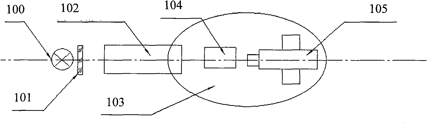
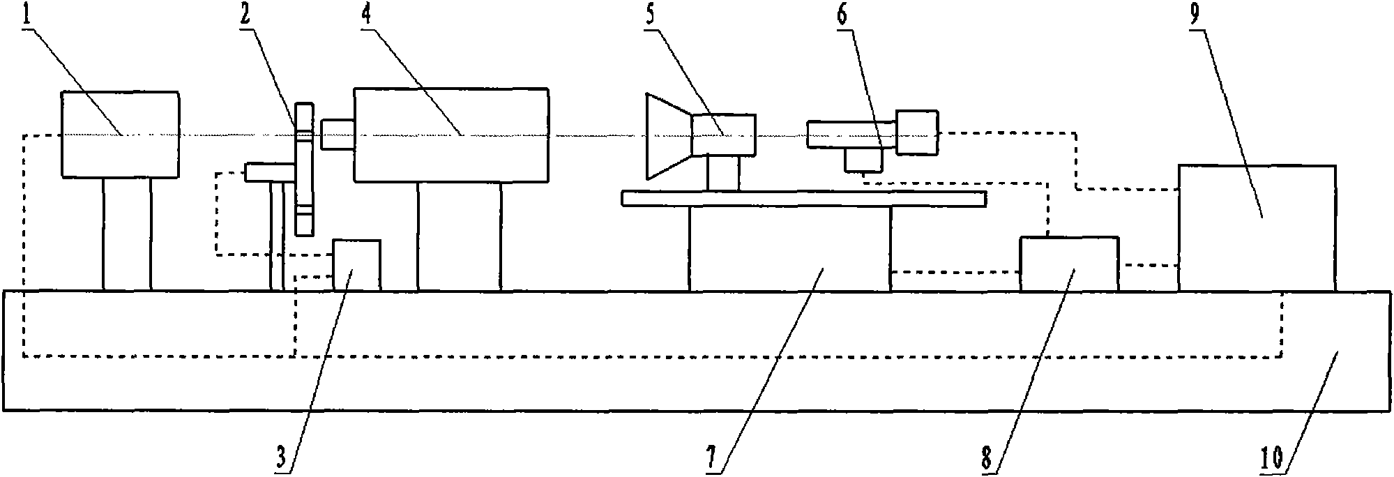
[0037] see figure 2, the sensor optical system diffuse spot and color deviation testing device provided by the present invention comprises a monochromator 1, a target target wheel 2, a target controller 3, a collimator 4, an optical system under test 5, and a two-dimensional CCD microscopic measurement Unit 6, digital display turntable 7, controller 8, acquisition and control computer 9, shock absorption platform 10; the spectral range of the monochromator 1 is required to be able to cover the spectral range of the measured optical system; the monochromator 1 is controlled by a computer, and the The target unit is illuminated; the target target wheel 2 and the target controller 3 form a target unit. The target target wheel 2 is equipped with a plurality of target plates on a disc at the same time, and its rotation is controlled by the target controller 3. It is mainly used for Provide star point targets of different sizes; the target target wheel 2 is connected to the target ...


PUM


Abstract

The invention relates to a testing device and method for the defocused spot and the color bias of an optical system, wherein the device comprises a monochromator, a target wheel, a collimator, a rotary table, a CCD (Charge-Coupled Device) micro-measuring unit and an acquisition and control computer; the monochromator, the target wheel, the collimator and the CCD micro-measuring unit are sequentially positioned on the same optical axis; the rotary table is used for arranging the tested optical system and the CCD micro-measuring unit; and the rotary table, the monochromator and the CCD micro-measuring unit are all connected with the acquisition and control computer. The invention can be used for effectively testing the defocused-spot diameters and the color biases of various optical systemswithin different wavelength ranges and well ensures the imaging quality of the optical systems.

Description

technical field [0001] The invention relates to a test device and method for the diffuse spot and color deviation of an optical system. Background technique [0002] The CCD star sensor is a high-precision optical sensor. It is an attitude sensor based on the star as a measurement reference. It mainly provides accurate information for the flight attitude and position of the spacecraft. The basic principle is to image a number of stars in the instantaneous field of view on the CCD photosensitive surface through the optical system, and through image processing and star catalog fitting, complete the identification of stars in the field of view, and then determine the current moment sensor light The orientation of the axis in the inertial coordinate system. Attitude measurement is realized through the measurement of the angular distance between stars, and the calculation accuracy of the center of the star image directly affects the measurement of the angular distance. This show...

Claims


Application Information

Patent Timeline
Patent Type & Authority Applications(China)
IPC IPC(8): G01M11/02
Inventor 周艳赵建科陈永权张洁徐亮
Owner XI'AN INST OF OPTICS & FINE MECHANICS - CHINESE ACAD OF SCI
Why Eureka
Try Eureka