Reflect array antenna

A reflective array antenna and reflective surface technology, which is applied in the field of communication, can solve the problems of poor low-frequency characteristics and achieve high-bandwidth effects

Active Publication Date: 2016-01-20
NAT SPACE SCI CENT CAS
View PDF4 Cites 17 Cited by
  • Summary
  • Abstract
  • Description
  • Claims
  • Application Information

AI Technical Summary

Problems solved by technology

[0004] The purpose of the present invention is to overcome the relatively poor low-frequency characteristics of

Method used


Image

  • Reflect array antenna
  • Reflect array antenna
  • Reflect array antenna

Examples


Embodiment Construction

[0024] The present invention will be further described now in conjunction with accompanying drawing.

[0025] The reflectarray antenna of the present invention includes: a feed pyramid horn and a reflector array; the feed pyramid horn is placed directly above the center of the reflector array; wherein,

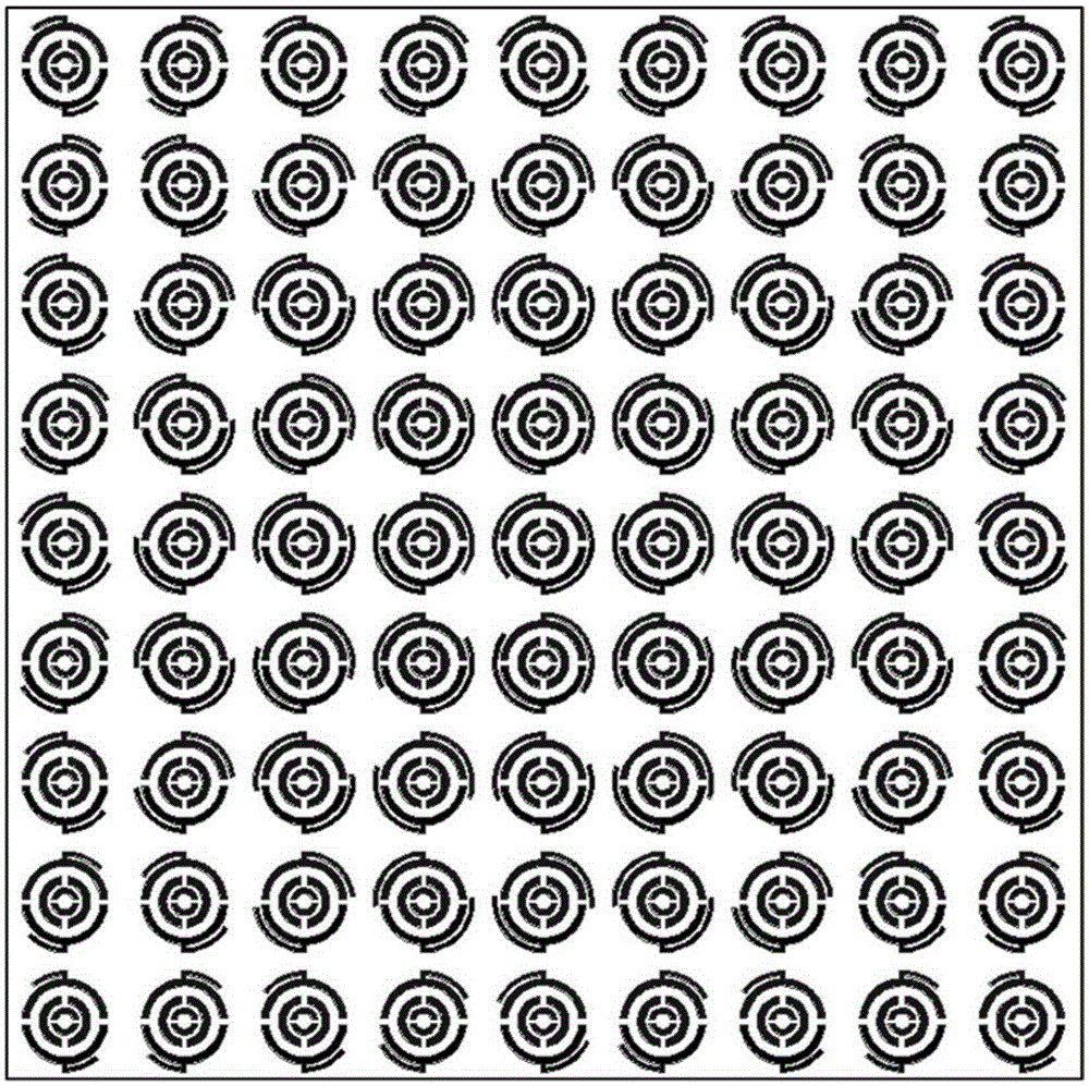
[0026] The reflector array is formed by a plurality of antenna units arranged periodically in a mirror-symmetrical manner;

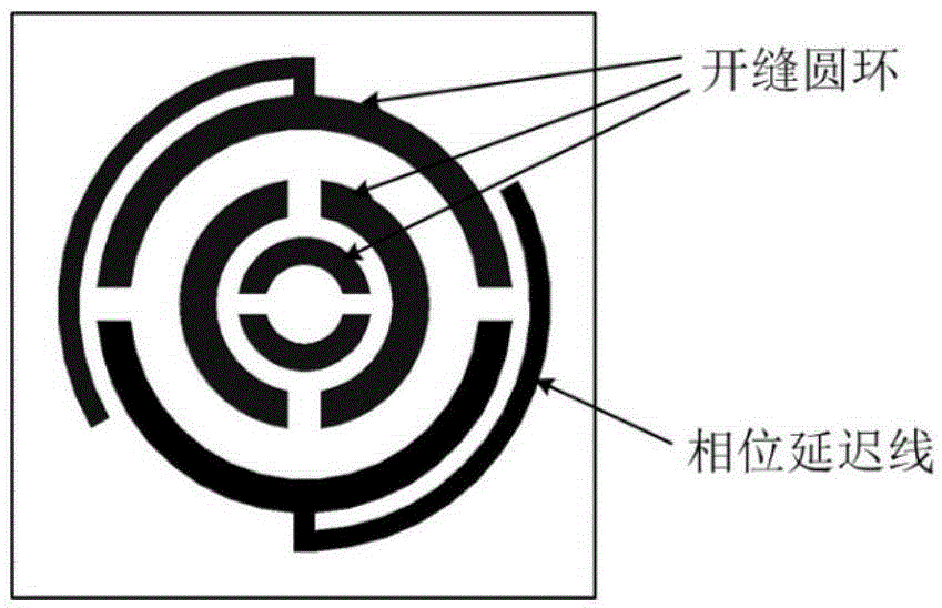
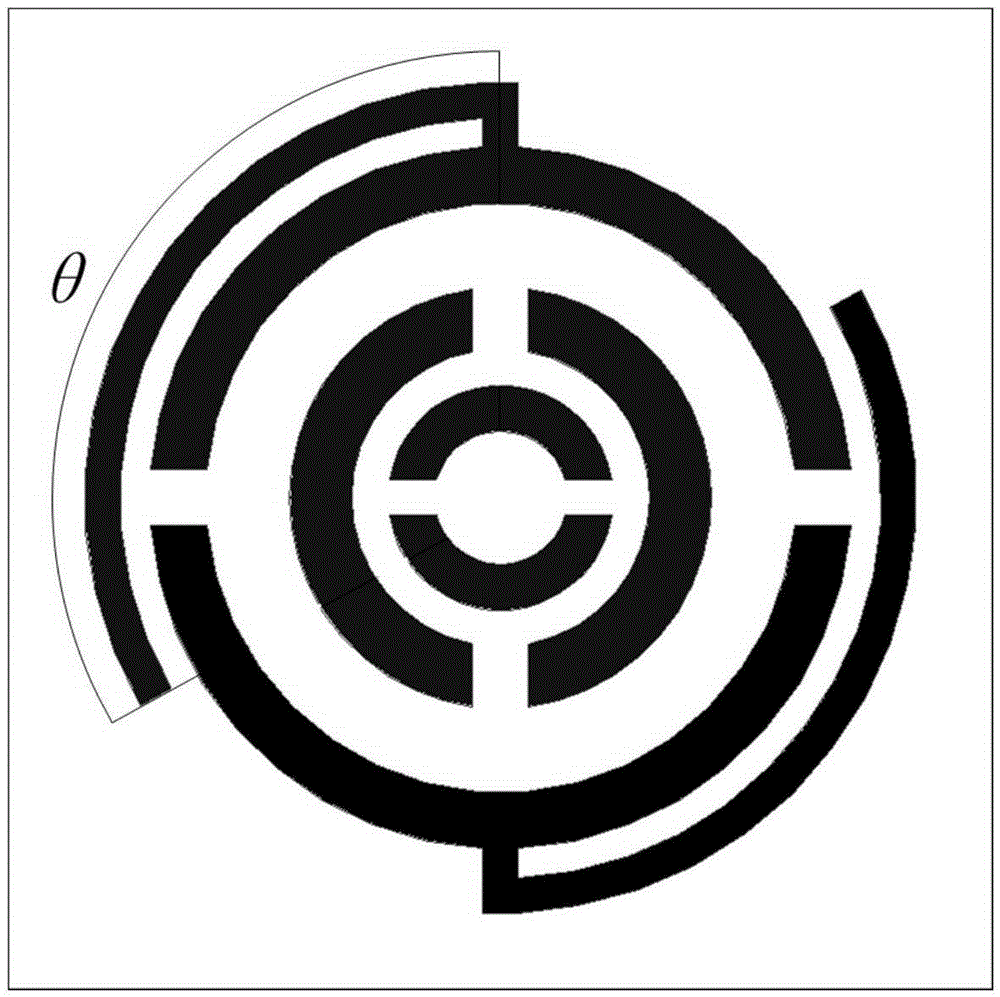
[0027] The antenna unit is improved compared with the existing phase delay line reflector unit, and specifically includes: a microstrip patch and a bottom plate; the microstrip patch is located on the bottom plate; as figure 2 As shown, the microstrip patch further includes: three nested rings and two phase delay lines; two slits symmetrical to the center are respectively set on the three rings.

[0028] exist figure 1 An embodiment of the reflector array in the reflectarray antenna of the present invention is given in , in this embodiment, 81 antenna...


PUM


Abstract

The invention relates to a reflect array antenna, which comprises a feed source pyramidal horn and a reflecting surface array, wherein the reflecting surface array is formed by periodically arranging a plurality of antenna units in a mirror symmetry manner in sequence; each antenna unit comprises a micro-strip patch and a bottom plate; the micro-strip patch is located on the bottom plate and further comprises nested three circular rings and two phase delay lines; two gaps which are centrally symmetrical relatively are formed in each of three circular rings; each of the two phase delay lines is in an arc form, and is connected with a micro-strip stub on the outer circular ring of the micro-strip patch; and the connecting line of the micro-strip stubs is parallel to a polarization direction of the antenna. According to the reflect array antenna, the reflect array antenna with a relatively high bandwidth can be achieved by combining the advantages of different structures.

Description

technical field [0001] The invention relates to the communication field, in particular to a reflection array antenna. Background technique [0002] In recent years, microstrip reflectarray antenna technology combines the outstanding features of parabolic antenna and microstrip array antenna, and has been widely developed and applied in the field of radar and communication. The advantage of the reflectarray antenna is that it does not require a complicated feeding network and can achieve high radiation efficiency. In addition, the design and processing of the reflectarray antenna is more convenient, light in weight, and low in cost. However, the reflectarray antenna also has some disadvantages, the most prominent of which is that its bandwidth is relatively narrow, generally less than 10%. There are two reasons for the low bandwidth of the reflectarray antenna: the first is the narrowband characteristics of the microstrip antenna unit itself, and the second is that the elect...

Claims


Application Information

Patent Timeline
IPC IPC(8): H01Q13/02H01Q15/14H01Q19/10
Inventor 韩春晖张云华杨青山
Owner NAT SPACE SCI CENT CAS
Why Eureka
Try Eureka