A two-phase interleaved magnetically integrated boost converter without right-half-plane zero point

A converter and magnetic integration technology, applied in the direction of converting DC power input to DC power output, instruments, adjusting electrical variables, etc., can solve the problems of limiting the power density of the converter, poor dynamic characteristics of the converter, etc., and improve the dynamic response speed. , the effect of increasing power density

Active Publication Date: 2018-01-19
HARBIN INST OF TECH SHENZHEN GRADUATE SCHOOL
View PDF5 Cites 0 Cited by
  • Summary
  • Abstract
  • Description
  • Claims
  • Application Information

AI Technical Summary

Problems solved by technology

The control loop crossing frequency of this non-minimum phase system needs to be lower than the frequency where the right half plane zero point is located to ensure sufficient phase angle margin of the loop, so the dynamic characteristics of this converter are poor
In addition, according to statistics, the cost of magnetic materials generally accounts for 30-40% of the DC-DC converter, and the weight generally accounts for about 20-30% of the whole. The filter inductance of each phase in the multi-phase also limits the power density of the converter. improve

Method used


Image

  • A two-phase interleaved magnetically integrated boost converter without right-half-plane zero point
  • A two-phase interleaved magnetically integrated boost converter without right-half-plane zero point
  • A two-phase interleaved magnetically integrated boost converter without right-half-plane zero point

Examples


Embodiment Construction

[0014] In order to make the object, technical solution and advantages of the present invention clearer, the present invention will be further described in detail below in conjunction with the accompanying drawings and embodiments. It should be understood that the specific embodiments described here are only used to explain the present invention, not to limit the present invention.

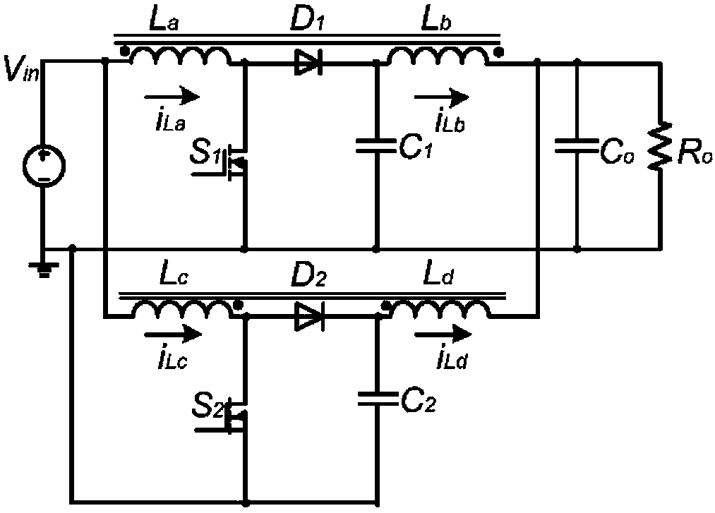
[0015] The topological structure of the two-phase interleaved reverse-phase coupled inductance-magnetic integrated boost converter of the present invention is as attached figure 1 shown, the inductance L a The opposite terminal and the inductance L b The dissenting ends are connected, the inductance L c Dotted terminal and inductance L d Connected to the terminal of the same name, the inductance L a Dotted terminal and inductance L c The dissenting ends are connected, the inductance L b Dotted terminal and inductance L d The opposite end of the switch is connected, the switch S 1 One end of...


PUM


Abstract

The invention provides a two-phase staggered magnetic integration boost converter. Inductances La and Lb, and inductances Lc and Ld form two phase respectively; the drive signals of switch tubes S1 and S2 mutually stagger with each other by 180 DEG; the inductances La, Lb, Lc and Ld share the same magnetic core; and La is coupled with Lb and Lc in the opposite direction, and is coupled with Ld in the forward direction. The invention also provides a condition for removing a right half plane zero point through a converter. When the parameter design is reasonable, the converter can satisfy the minimum phase system within the wide duty ratio working range, and can greatly improve the dynamic response speed of the converter. Except for the above advantages, the output filtering inductances are integrated in the same magnetic core and the power density of the converter can be greatly improved.

Description

technical field [0001] The invention relates to the technical field of DC-DC converters, in particular to a two-phase interleaved magnetically integrated boost converter. Background technique [0002] When the traditional multi-phase interleaved parallel boost works in CCM mode, the control-output transfer function contains a right-half plane zero. The control loop crossing frequency of this non-minimum phase system needs to be lower than the frequency where the right half plane zero point is located to ensure that the loop has sufficient phase angle margin, so the dynamic characteristics of this converter are poor. In addition, according to statistics, the cost of magnetic materials generally accounts for 30-40% of the DC-DC converter, and the weight generally accounts for about 20-30% of the whole. The filter inductance of each phase in the multi-phase also limits the power density of the converter. improve. Contents of the invention [0003] In order to solve the prob...

Claims


Application Information

Patent Timeline
Patent Type & Authority Patents(China)
IPC IPC(8): H02M3/155
Inventor 张东来刘贺
Owner HARBIN INST OF TECH SHENZHEN GRADUATE SCHOOL
Why Eureka
Try Eureka