Material belt joining assembly and material belt splicing method using the same

A tape and component technology, applied in the field of electronic component carrier tape, can solve the problems of reduced equipment utilization rate, low convenience, automatic placement machine jamming, etc., to shorten the splicing time, avoid manual errors, and pass rate-boosting effect

Inactive Publication Date: 2016-01-20
AMERICAN TEC CO LTD
View PDF8 Cites 1 Cited by
  • Summary
  • Abstract
  • Description
  • Claims
  • Application Information

AI Technical Summary

Problems solved by technology

[0005] 1) Special tools must be used, which is less convenient;
[0006] 2), the operation is time-consuming, and even has to be shut down to wait, reducing the equipment utilization rate;
[0007] 3) The existing horizontal shearing method has a certain failure rate (about 15%~25%), resulting in double loss (manpower and equipment loss)
Although there are also a few who use semi-automatic belt splicing machines to increase the success rate, it still takes a long time and the machine tool itself is not convenient to place and move;
[0008] 4) After the splicing of the two tapes, it is easy to bend at a right angle along the splicing line, and it is easy to cause jamming when used in an automatic placement machine

Method used


Image

  • Material belt joining assembly and material belt splicing method using the same
  • Material belt joining assembly and material belt splicing method using the same
  • Material belt joining assembly and material belt splicing method using the same

Examples


Embodiment Construction

[0027] The present invention will be described in detail below in conjunction with the accompanying drawings and specific embodiments.

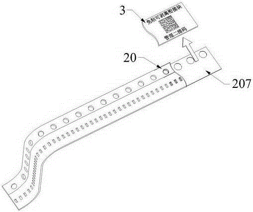
[0028] see figure 2 , the present invention provides a material tape connecting assembly, the material tape connecting assembly includes a non-adhesive and peelable connecting block 3 spliced ​​with the end of the material tape 20, a reinforcing tape 207, and one side of the connecting block 3 is glued to the reinforcing tape 207 , the length of the reinforcing tape 207 is greater than the length of the connecting block 3 .

[0029] The splicing part of the connecting block 3 is in an S configuration; the corresponding end of the material strip spliced ​​with it is also in an S configuration.

[0030] The connecting block 3 is provided with barcodes on both sides.

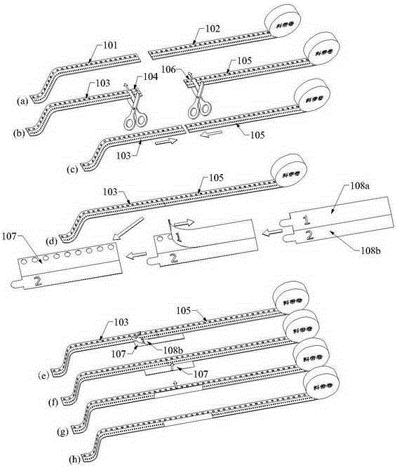
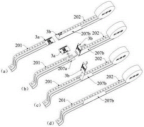
[0031] see image 3 , the present invention also provides a strip splicing method using the above-mentioned strip joint assembly, the specific technical scheme is as follows: ...


PUM


Abstract

The invention discloses a material belt joining assembly and a material belt splicing method using the same. The material belt joining assembly comprises an adhesive-free strippable joining block jointed to the end part of a material belt and a reinforcing adhesive tape. One face of the joint block is adhered to the reinforcing adhesive tape. The length of the reinforcing adhesive tape is larger than the length of the joint block. The material belt splicing method comprises the step that joint blocks are gradually removed from two material belts whose end parts use the material joining assembly, so firm splicing of the material belts are achieved. The beneficial effects are that 1) splicing time of the material belts is greatly reduced; 2) via the S-shaped cutting, contact length of the splicing and support force of splicing faces are increased, the material belts will not be bent in right angle when external force is imposed on the spliced place, and the passing rate is much high when the spliced material belts are used in an automatic surface mount device; 3) in the splicing process, any cutting tool is not required and manual errors generated in cutting can be avoided; and 4) by managing colors, labels or bar codes on the surfaces of the joint blocks and then adding necessary information, false materials can be avoided.

Description

technical field [0001] The present invention relates to electronic element carrier tape, in particular to a tape joint assembly and a tape splicing method using the tape joint assembly. The tape joint assembly is used to splice old and new tapes together for use. Background technique [0002] Component mounting tape is the largest and most important feeding method for SMT in the electronic assembly industry. More than 90% of placement machines rely on tape feeding. When a roll of tape is supplied, a new tape needs to be connected. Cut the tail end of the old tape and the front end of the new tape, and align the covering stickers for connection. Skilled operators are required to operate, and there is a certain failure rate. [0003] figure 1 (a) to (h) are schematic diagrams of the process of connecting new and old material belts in the prior art. 101 is the old material belt, and 102 is the new material belt. Cut off the material strip 104 vertically along the center line...

Claims


Application Information

Patent Timeline
Patent Type & Authority Applications(China)
IPC IPC(8): H05K13/02
Inventor 张永泰胡就桥谢金兴张建光李欣桐
Owner AMERICAN TEC CO LTD
Why Eureka
Try Eureka