A steel bar connection assembly for bearing pile construction of high-rise buildings
A technology for connecting components and buildings. It is applied in the direction of building components, building reinforcements, building structures, etc. It can solve the problems that the strength cannot meet the requirements of building construction and detachment, so as to ensure clamping strength, simple operation, and reduce wear. Effect
- Summary
- Abstract
- Description
- Claims
- Application Information
AI Technical Summary
Problems solved by technology
Method used
Image
Examples
Embodiment 1
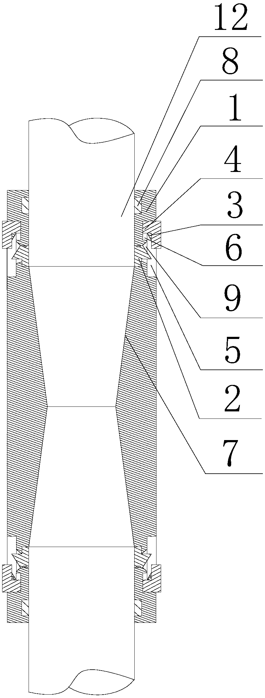
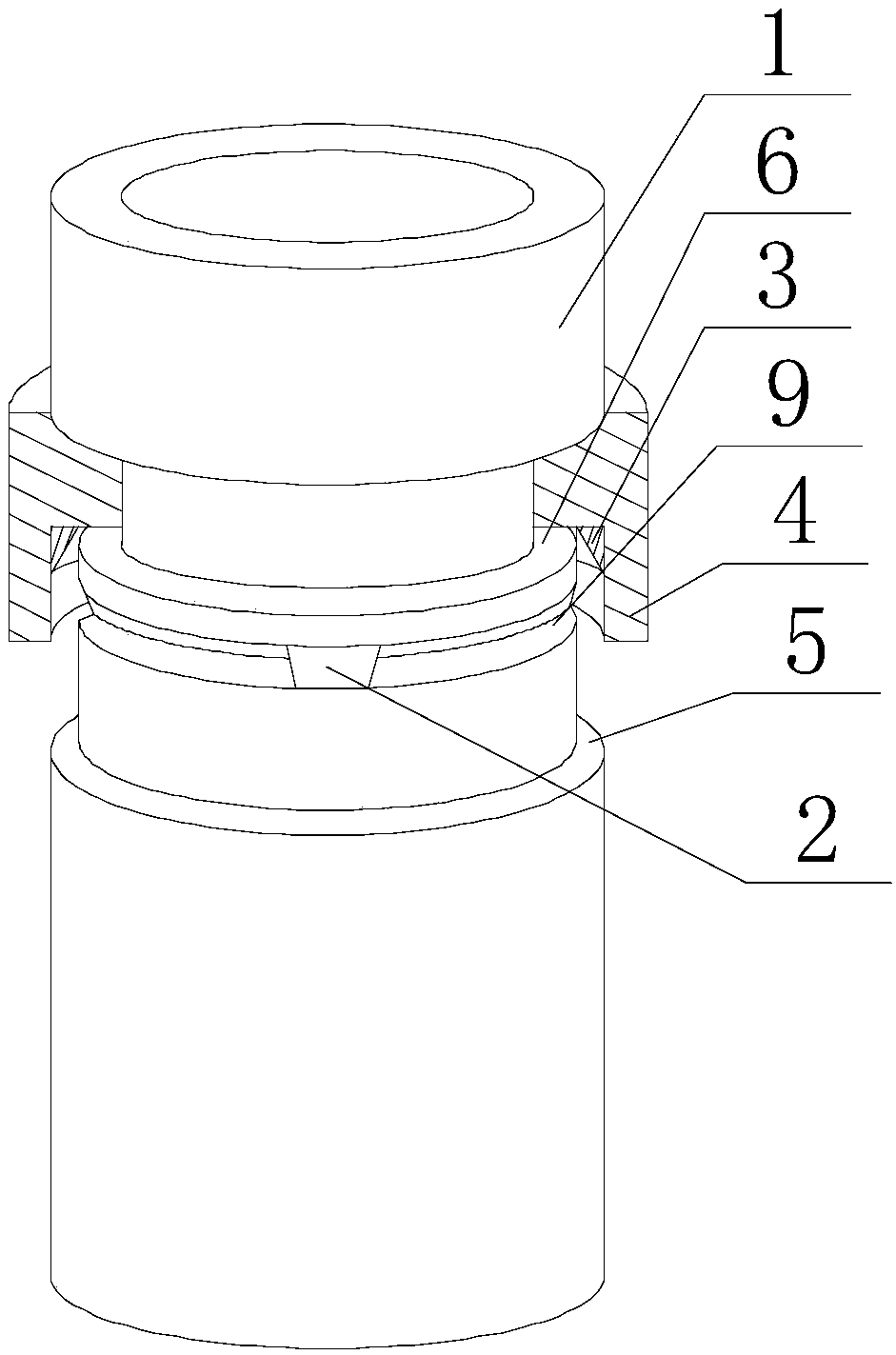
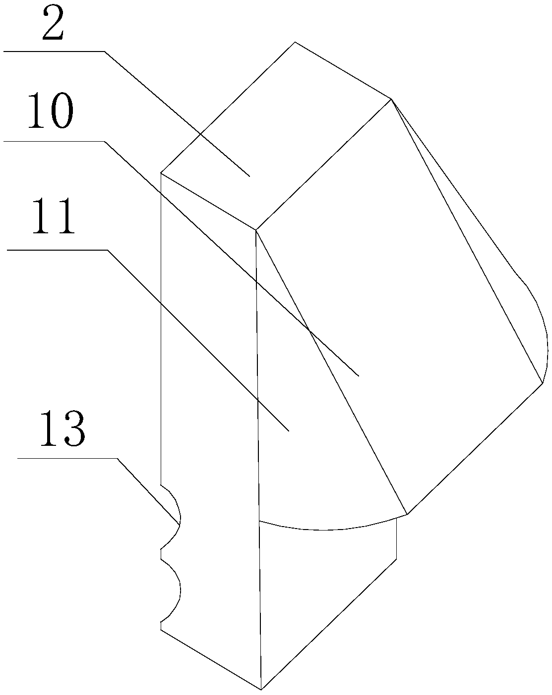
[0027] Such as Figure 1~3As shown, this embodiment includes a connecting cylinder 1 and a snap ring 7 fixed on the outer peripheral wall of one end of the connecting cylinder 1. A nut 8 threadedly fitted with the connecting cylinder 1 is provided on the connecting cylinder 1, and the nut 8 and the snap ring 7 Located on the same side of the connecting cylinder 1, a chute 6 is provided on the outer peripheral wall of the other end along the circumferential direction of the connecting cylinder 1, and a chute 6 is opened on the outer peripheral wall of the connecting cylinder 1 along the circumferential direction. Connected limit groove 5, and an annular groove 9 is provided at the bottom of the groove along the circumferential direction of the chute 6, at least one through hole communicating with the inside of the connecting cylinder 1 is opened on the annular groove 9, and the pressure block 2 is hinged by a torsion spring. In the through hole, and the inner side wall of the p...
Embodiment 2
[0031] Such as Figure 1~3 As shown, the longitudinal section of the annular groove 9 in this embodiment is triangular. Since the outer wall of the pressure block 2 partially protrudes from the annular groove 9, and the cross-section of the protrusion is also triangular, so that the protrusion 3 moves to contact with the outer wall of the contact block 10 and squeezes it, and the protrusion is compressed. The hinge point rotates, so that the protrusion moves into the annular groove 9, and the rotation of the snap ring is stopped. At this time, the annular protrusion 3 continues to squeeze the pressure block 2, and the inner side wall of the pressure block 2 continues to hold the main rib 12. Hold, because the inner diameter of the protrusion 3 is in an increasing state, that is, the longitudinal section of the partial section of the protrusion 3 is triangular, and the contact block 10 matched with the protrusion 3 rotates at a relatively large angle in the annular groove 9 who...
PUM
 Abstract
Description
Claims
Application Information
 - R&D
- Intellectual Property
- Life Sciences
- Materials
- Tech Scout
- Unparalleled Data Quality
- Higher Quality Content
- 60% Fewer Hallucinations
Browse by: Latest US Patents, China's latest patents, Technical Efficacy Thesaurus, Application Domain, Technology Topic, Popular Technical Reports.
© 2025 PatSnap. All rights reserved.Legal|Privacy policy|Modern Slavery Act Transparency Statement|Sitemap|About US| Contact US: help@patsnap.com


