Fish pond bait throwing-in device

A feeding device and bait technology, which is applied in fish farming, application, animal husbandry, etc., can solve problems such as easy blockage of pipelines, uneven material distribution, and danger, and achieve turbulent flow, stable fluid flow, and wind energy. low loss effect

Inactive Publication Date: 2016-01-27
NANJING UNIV OF AERONAUTICS & ASTRONAUTICS
View PDF6 Cites 5 Cited by
  • Summary
  • Abstract
  • Description
  • Claims
  • Application Information

AI Technical Summary

Problems solved by technology

[0002] There are still many fish pond feeding devices that set the feeding point on the workbench by the lake. Every time you need to feed the bait, you must first move the bait to the workbench, which makes the workbench slippery in rainy weather. Sometimes, it will be dangerous to feed again, and it is easy to fall or even fall into the lake
[0003] Feeding with long pipes generally has two methods: vacuum air suction and blast air blowing, but for vacuum air suction, the equipment needs to be installed in the center of the fish pond, which is not conducive to maintenance, and it is easy to be damaged by wind and rain
There are two problems that need to be solved when using long pipeline feeding: one is that the pipeline is easy to block, and the other is that the material distribution is uneven
If the bait in the feeding pipe falls too much at once into the feeding pipe, it will easily cause blockage. At this time, inspection and maintenance will be troublesome, time-consuming and laborious
If one blower corresponds to one spray table, there is no problem of material distribution, but this can only be applied to a small area or a single fish pond
If one blower corresponds to several spraying stations, although it can be applied to larger fish ponds, it is inevitable that the bait will be unevenly distributed when it is sent to each spraying station
[0004] There are still two problems in using the air blowing method. One is that when the bait is put into the pipeline, due to the wind pressure in the pipeline, it is easy to make the gravity of the bait less than the pressure so that it cannot fall freely in the pipeline; There is also a blockage in the pipeline, which prevents the bait from falling

Method used


Image

  • Fish pond bait throwing-in device
  • Fish pond bait throwing-in device
  • Fish pond bait throwing-in device

Examples


Embodiment 1

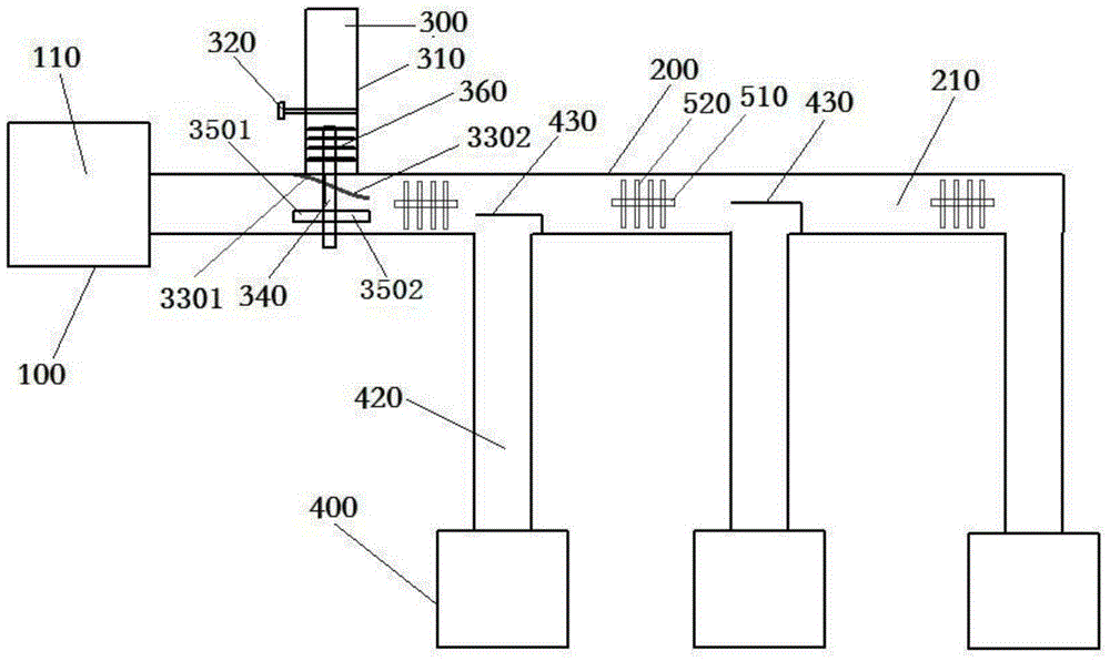
[0056] Such as figure 1 As shown, the fishpond bait feeding device of the present invention includes a blast system 100 , a feeding system 200 , a feeding system 300 and a material spraying system 400 .

[0057] In one embodiment, the blowing system 100 includes a blower 110 with a power of 750W, and the feeding system 200 includes a feeding pipe 210, one end of the feeding pipe 210 is connected with the blower 110, and the blower 110 introduces external air into the feeding pipe 210 .

[0058] In another embodiment, the blower system may include multiple blowers.

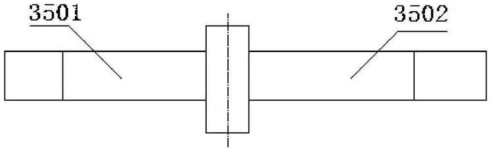
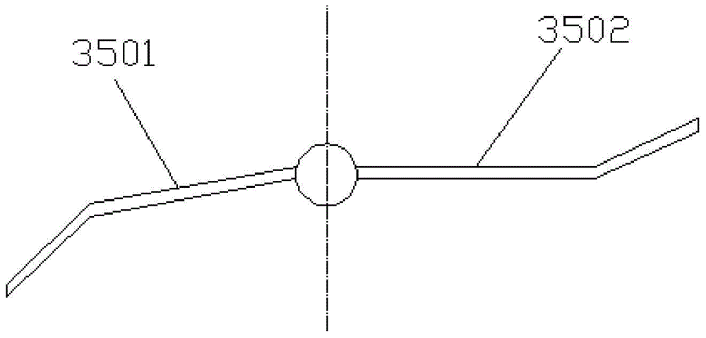
[0059] exist figure 1 Among them, the feeding system 300 includes a feeding pipe 310, a flow controller 320, a windshield 330, a stirring shaft 340, a first stirring blade 3501, a second stirring blade 3502 and a stirring tooth 360; wherein the feeding pipe 310 is arranged on On the end of the feeding pipe 210 close to the blower 100, the feeding pipe 310 is placed vertically, allowing the bait to fall into the ...

Embodiment 2

[0083] Such as figure 1 As shown, the fishpond bait feeding device of the present invention includes a blast system 100 , a feeding system 200 , a feeding system 300 and a material spraying system 400 .

[0084] In one embodiment, the blowing system 100 includes a blower 110 with a power of 750W, and the feeding system 200 includes a feeding pipe 210, one end of the feeding pipe 210 is connected with the blower 110, and the blower 110 introduces external air into the feeding pipe 210 .

[0085] In another embodiment, the blower system may include multiple blowers.

[0086] exist figure 1 Among them, the feeding system 300 includes a feeding pipe 310, a flow controller 320, a windshield 330, a stirring shaft 340, a first stirring blade 3501, a second stirring blade 3502 and a stirring tooth 360; wherein the feeding pipe 310 is arranged on On the end of the feeding pipe 210 close to the blower 100, the feeding pipe 310 is placed vertically, allowing the bait to fall into the ...

Embodiment 3

[0110] Such as figure 1 As shown, the fishpond bait feeding device of the present invention includes a blast system 100 , a feeding system 200 , a feeding system 300 and a material spraying system 400 .

[0111] In one embodiment, the blower system 100 includes a blower 110 with a power of 750W, and the feeding system 200 includes a feeding pipe 210, one end of the feeding pipe 210 is connected with the blower 110, and the blower 110 introduces external air into the feeding pipe 210 .

[0112] In another embodiment, the blower system may include multiple blowers.

[0113] exist figure 1 Among them, the feeding system 300 includes a feeding pipe 310, a flow controller 320, a windshield 330, a stirring shaft 340, a first stirring blade 3501, a second stirring blade 3502 and a stirring tooth 360; wherein the feeding pipe 310 is arranged on On the end of the feeding pipe 210 close to the blower 100, the feeding pipe 310 is placed vertically, allowing the bait to fall into the f...


PUM


Abstract

The invention provides a fish pond bait throwing-in device, which comprises an air blasting system, a conveying system, a feeding system and a spraying system, wherein the feeding system further comprises a wind board, a stirring shaft and stirring blades, the wind board forms a covering space at a connecting port of a feeding pipe and a conveying pipe, the stirring shaft is located at the bottom part of the feeding pipe, extends downward and penetrates through the wind board and the conveying pipe, and the stirring blades are fixedly connected on the stirring shaft and can drive the stirring shaft to rotate. The fish pond bait throwing-in device has the advantages of abilities of preventing blockage of the feeding pipe, preventing inability of bait for falling into the conveying pipe, preventing uneven distribution of spraying platforms, increasing oxygen in water, being applicable to a large-area fish pond or multiple fish ponds, and the like.

Description

technical field [0001] The invention relates to a bait feeding device, in particular to a bait feeding device for fish ponds. Background technique [0002] There are still many fish pond feeding devices that set the feeding point on the workbench by the lake. Every time you need to feed the bait, you must first move the bait to the workbench, which makes the workbench slippery in rainy weather. Sometimes, it will be dangerous to feed again, and it is easy to fall or even fall into the lake. [0003] Feeding with long pipes generally has two methods: vacuum air suction and blast air blowing, but for vacuum air suction, the equipment needs to be installed in the center of the fish pond, which is not conducive to maintenance, and it is easy to be damaged by wind and rain. There are two problems to be solved when using a long pipeline for feeding: one is that the pipeline is easy to block, and the other is that the material is not evenly distributed. If the bait in the feeding...

Claims


Application Information

Patent Timeline
Patent Type & Authority Applications(China)
IPC IPC(8): A01K61/02
Inventor 刘奕荣
Owner NANJING UNIV OF AERONAUTICS & ASTRONAUTICS
Why Eureka
Try Eureka