Controllable milling end face clamp for batches of workpieces

An end face milling, controllable technology, applied in the direction of manufacturing tools, metal processing machinery parts, clamping, etc., can solve the problems of inconvenient operation, difficult workpiece clamping quantity control, low efficiency, etc., to achieve the effect of easy control

Inactive Publication Date: 2016-01-27
WUHU TAINENG ELECTRIC APPLIANCES
View PDF6 Cites 2 Cited by
  • Summary
  • Abstract
  • Description
  • Claims
  • Application Information

AI Technical Summary

Problems solved by technology

[0002] Generally speaking, many small parts often need to be milled on the upper end surface after processing, but the traditional fixture can only fix and clamp a single part at one time, which leads to only one part at a time. , low efficiency
Although there are some fixtures that can clamp multiple workpieces at one time to facilitate one-time milling, such fixtures are either inconvenient to operate or difficult to effectively and conveniently control the number of clamped workpieces.

Method used


Image

  • Controllable milling end face clamp for batches of workpieces
  • Controllable milling end face clamp for batches of workpieces

Examples


Embodiment Construction

[0014] In order to make the technical means, creative features, goals and effects achieved by the present invention easy to understand, the present invention will be further elaborated below.

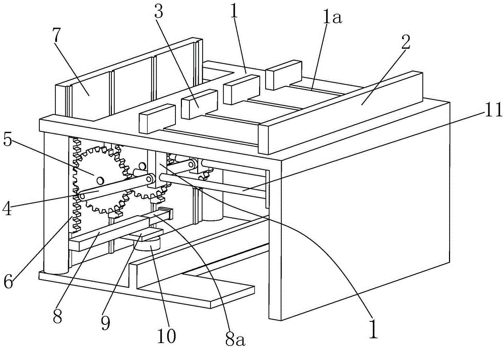
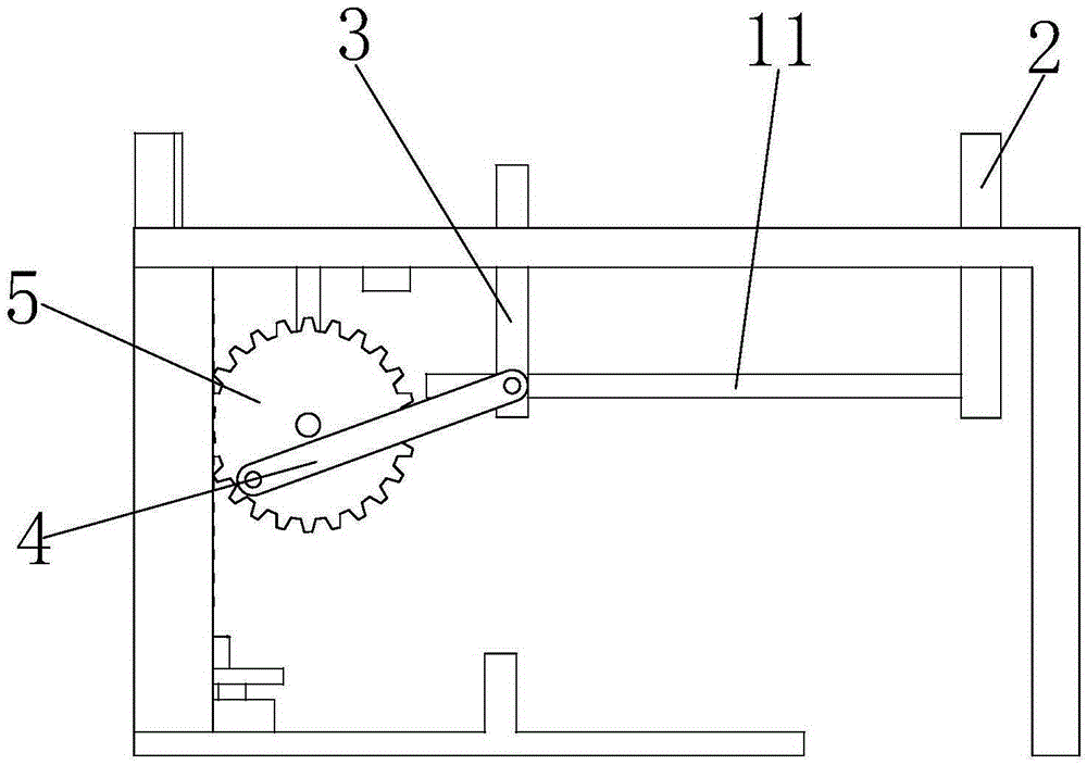
[0015] Such as Figure 1 to Figure 2 As shown, a controllable batch workpiece milling end face fixture mainly includes a workbench 1 on which four chutes 1a are evenly distributed along the horizontal direction, and the right end of the chute 1a is provided with a positioning plate 2 , the clamping plates 3 are slidably installed in the chute 1a.

[0016] The lower end of the clamping plate 3 is hinged with a connecting rod 4, and the connecting rod 4 has a gear 5 on the left. The left end of the connecting rod 4 is hingedly mounted on the edge of the gear 5. A rack 6 is meshed, and the left side of the rack 6 is provided with a fixed plate 7 for slidingly installing the rack 6 in the longitudinal direction. There is an adapter plate 8 below the rack 6, and the inside of the adapter pl...


PUM


Abstract

The invention relates to a controllable milling end face clamp for batch of workpieces. The controllable milling end face clamp comprises a workbench, wherein four sliding grooves uniformly distributed in the workbench on the horizontal direction; a positioning plate is arranged at the right end of each sliding groove, and a clamping plate is mounted in each sliding groove in a sliding manner; the lower end of each clamping plate is articulated with a connecting rod, and a gear is arranged on the left side of each connecting rod; the left end of each connecting rod is articulated at the edge end of each gear, and the left side of each gear is meshed with a rack; a fixing plate for longitudinally mounting each rack in a sliding manner is arranged on the left side of each rack, and an adapter plate is arranged under each rack; a transiting extending end is mounted at the rear end in each adapter plate in a sliding manner, a push plate for fixedly mounting the adapter plate is arranged at the lower end of each adapter plate, and the lower end of the push plate is connected with an air cylinder. The controllable milling end face clamp can quickly clamp multiple workpieces in one time in a high automation way, and can also effectively control the quantity of the clamping workpieces through the fore-and-aft sliding of the transiting extending ends, therefore indirectly achieving the effects that the milling quantity of workpieces is conveniently controlled and the processing speed is increased.

Description

technical field [0001] The invention relates to the field of clamps, in particular to a controllable batch workpiece milling end face clamp. Background technique [0002] Generally speaking, many small parts often need to be milled on the upper end surface after processing, but the traditional fixture can only fix and clamp a single part at one time, which leads to only one part at a time. , the efficiency is low. Although there are currently some fixtures that can clamp multiple workpieces at one time to facilitate one-time milling, such fixtures are either inconvenient to operate or difficult to effectively and conveniently control the number of clamped workpieces. Contents of the invention [0003] In view of the defects of the above-mentioned technologies, the present invention proposes a controllable batch workpiece milling end face fixture that can quickly clamp workpieces and the number of clamped workpieces can be controlled. [0004] A controllable end-face mill...

Claims


Application Information

Patent Timeline
Patent Type & Authority Applications(China)
IPC IPC(8): B23Q3/08
CPCB23Q3/08B23Q2703/08
Inventor 付建邹洪
Owner WUHU TAINENG ELECTRIC APPLIANCES
Why Eureka
Try Eureka