Fixture for milling end faces of workpieces in batches

A technology for milling end faces and workpieces, which is applied in the field of batch workpiece milling end face fixtures, can solve the problems of inconvenience and low efficiency, and achieve the effect of convenient operation and easy control

Inactive Publication Date: 2016-01-27
WUHU TAINENG ELECTRIC APPLIANCES
View PDF5 Cites 26 Cited by
  • Summary
  • Abstract
  • Description
  • Claims
  • Application Information

AI Technical Summary

Problems solved by technology

[0002] Generally speaking, many small parts often need to be milled on the upper end surface after processing, but the traditional fixture can only fix and clamp a single part at one time, which leads to only one part at a time. , low efficiency
Although there are currently some fixtures that can clamp multiple workpieces at one time to facilitate one-time milling, it is often inconvenient for the operator to clamp the workpieces one by one when using them.

Method used


Image

  • Fixture for milling end faces of workpieces in batches
  • Fixture for milling end faces of workpieces in batches
  • Fixture for milling end faces of workpieces in batches

Examples


Embodiment Construction

[0015] In order to make the technical means, creative features, goals and effects achieved by the present invention easy to understand, the present invention will be further elaborated below.

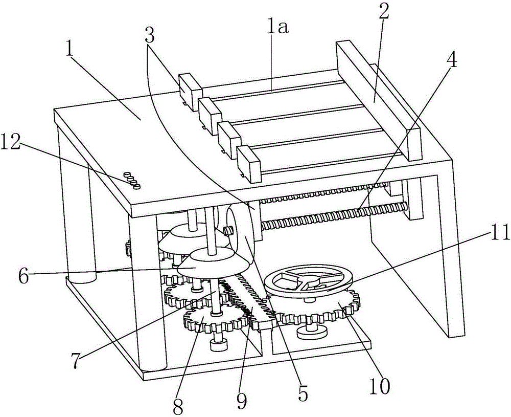
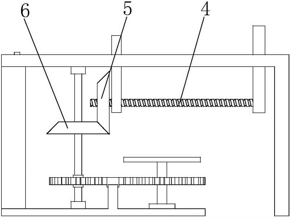
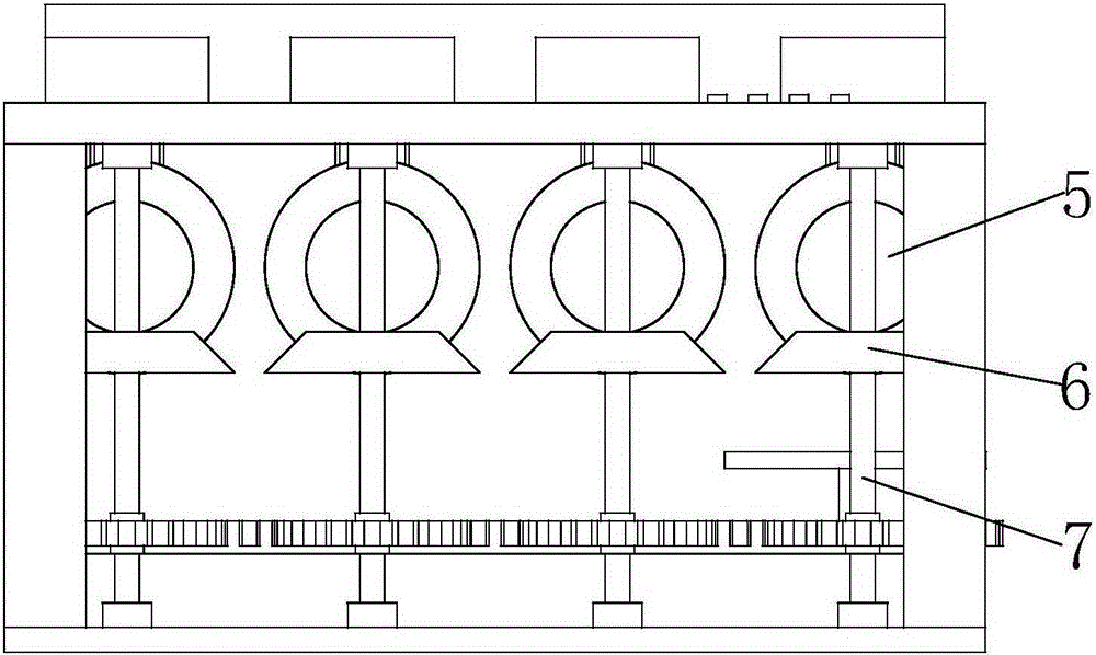
[0016] Such as Figure 1 to Figure 3 As shown, a batch workpiece milling end face fixture mainly includes a workbench 1, and four chutes 1a are evenly distributed along the front and rear directions on the workbench 1, and a positioning plate 2 is provided at the right end of the chute 1a. Clamping plates 3 are slidably installed in the chute 1a.

[0017] The lower end of the clamping plate 3 is connected with a horizontally arranged ball screw 4, and the left end of the ball screw 4 is connected with a No. 1 bevel gear 5, and the No. 1 bevel gear 5 is meshed with a No. 2 bevel gear 6. The No. 2 bevel gear 6 is connected with a rotating shaft 7, the bottom of the rotating shaft 7 is connected with a clutch gear 8, and the right end of the clutch gear 8 is engaged with a double-sided ra...


PUM


Abstract

The invention relates to a fixture for milling end faces of workpieces in batches. The fixture mainly comprises a workbench, wherein four sliding grooves are formed in the workbench in front and back; a positioning plate block is arranged at the right ends of the sliding grooves; clamping plates are mounted in the sliding grooves in a sliding manner; the lower ends of the clamping plates are connected with ball screws horizontally arranged; the left ends of the ball screws are connected with bevel gears I; the bevel gears I are meshed with bevel gears II; the bevel gears II are connected with rotating shafts; the lower parts of the rotating shafts are connected with clutch gears; the right ends of the clutch gears are meshed with a double-side rack mounted below the workbench in the manner of sliding front and back; the right end of the double side rack is meshed with a driving gear; and the driving gear is connected with a rotary table. The fixture provided by the invention not only has the function of quickly clamping multiple workpieces at one time in a convenient and rapid operation mode and a gear meshing transmission mode, but also can effectively control the number of clamped workpieces and further can indirectly realize the effects of controlling milling number of workpiecess and increasing the processing speed.

Description

technical field [0001] The invention relates to the field of clamps, in particular to a batch workpiece milling end face clamp. Background technique [0002] Generally speaking, many small parts often need to be milled on the upper end surface after processing, but the traditional fixture can only fix and clamp a single part at one time, which leads to only one part at a time. , the efficiency is low. Although there are currently some fixtures that can clamp multiple workpieces at one time to facilitate one-time milling, it is often inconvenient for the operator to clamp the workpieces one by one when using them. Contents of the invention [0003] Aiming at the defects of the above-mentioned technologies, the present invention proposes a batch workpiece milling end face fixture which can be conveniently operated and clamp multiple workpieces at one time. [0004] A fixture for milling end faces of workpieces in batches, mainly including a workbench, on which four chutes ...

Claims


Application Information

Patent Timeline
Patent Type & Authority Applications(China)
IPC IPC(8): B23Q3/06
CPCB23Q3/061
Inventor 付建邹洪
Owner WUHU TAINENG ELECTRIC APPLIANCES
Why Eureka
Try Eureka