Open-end spinning machine

A free-end, rotor technology, which is applied in the directions of free-end spinning machines, spinning machines, and continuously wound spinning machines, can solve the problems of expensive production and production cost defects.

Active Publication Date: 2016-01-27
SAURER GERMANY GMBH & CO KG
View PDF6 Cites 0 Cited by
  • Summary
  • Abstract
  • Description
  • Claims
  • Application Information

AI Technical Summary

Problems solved by technology

[0009] Open-end spinning devices as described in DE2348064C2 have been used in practice for a long time, but still have the disadvantage that they are designed so that they are relatively expensive to produce, in other words, complex parts are made of light metal alloys
In these open-end spinning devices, which have been known for a long time, having many complex parts made of light metal alloys is also a significant disadvantage in terms of production costs

Method used


Image

  • Open-end spinning machine
  • Open-end spinning machine
  • Open-end spinning machine

Examples


Embodiment Construction

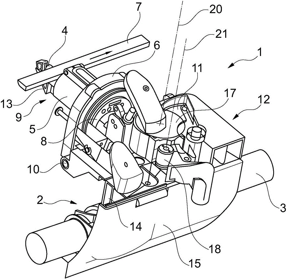
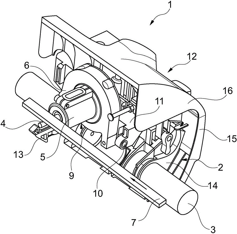
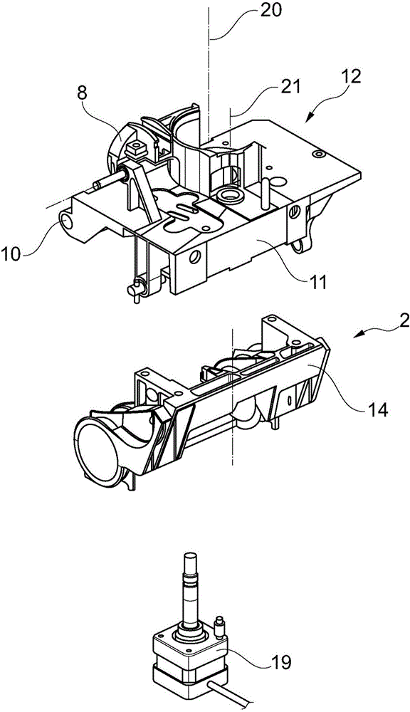
[0029] figure 1 A perspective front view of an open-end spinning device 1 is shown, which is arranged in each case in the region of a workstation of an open-end rotor spinning machine. The open-end spinning device 1 is pivotally mounted via its support mechanism 2 on a stationary support shaft 3 substantially along the length of the machine. In this embodiment, the spinning rotor, which is not shown in more detail for reasons of clarity, is mounted rotatably with its rotor shaft 4 in the direct bearing 5 and is tangentially rotated along the length of the machine. Driven by the belt 7, the rotor shaft 4 rests against the rotary tangential belt 7 from below. from figure 1 It can also be seen that the rotor housing 6 is closed by the cover element 8 or by a seal integrated in the cover element 8 , the spinning rotor of the spinning rotor being in the rotor housing 6 during the spinning process with High speed rotation.

[0030] In this embodiment, the direct bearing mechanis...


PUM


Abstract

The invention relates to an open-end spinning machine (1) having a spinning rotor. A rotor shaft (4) of the spinning rotor is supported in a rotor shaft support member (9) and can be driven by a rotary tangential belt (7) along the machine length. A spinning rotor body of the spinning rotor can be loaded in a rotor housing (6) of negative pressure to rotate at a high rotational speed during spinning. The rotor housing (6) can be covered by a cover member (8). The cover element (8) is a part of a housing (11) of a fibrous band opening mechanism (12). The fiber band opening mechanism (12) has a support mechanism (2). According to the invention, the housing (11) of the fiber band opening mechanism (12) and a housing (14) of the support mechanism (2) are two separate parts made of different materials, wherein the housing (11), associated with spinning, of the fiber band opening mechanism (12) is made of light metal alloy, and the housing (14) of the support mechanism (2) is made of plastic material.

Description

technical field [0001] The invention relates to an open-end spinning device with a spinning rotor whose rotor shaft is supported in a rotor shaft bearing element and can be driven by a revolving tangential belt along the length of the machine, which The rotor body of the spinning rotor rotates at high speed during the spinning operation in a rotor housing that can be subjected to a negative pressure and is closed by a cover element, which is the fiber ribbon opening mechanism parts of the shell. The rotor shaft bearing element is mounted and connected to the housing of the ribbon opening mechanism via a pivot shaft in such a way that when the open-end spinning device is opened, the rotor shaft is displaced to its Said turns along the length of the machine are tangential to the point where the belt disengages. Furthermore, the fiber ribbon opening mechanism has a bearing mechanism, via which the fiber ribbon opening mechanism is pivotably connected to a stationary bearing sha...

Claims


Application Information

Patent Timeline
IPC IPC(8): D01H4/08
CPCD01H4/32
Inventor 克劳迪娅·佳尔维茨拉尔夫·西韦特
Owner SAURER GERMANY GMBH & CO KG
Why Eureka
Try Eureka