Keyhole concealed lockset and lock liner device

A hidden, keyhole technology, used in building locks, door/window accessories, handle connections, etc., can solve problems such as the aesthetic impact of locks

Inactive Publication Date: 2016-01-27
ZHAOQING KAIDA HARDWARE DECORATION CO LTD
View PDF5 Cites 2 Cited by
  • Summary
  • Abstract
  • Description
  • Claims
  • Application Information

AI Technical Summary

Problems solved by technology

[0003] However, these two methods are still easy to find the position of the keyh

Method used


Image

  • Keyhole concealed lockset and lock liner device
  • Keyhole concealed lockset and lock liner device
  • Keyhole concealed lockset and lock liner device

Examples


Embodiment 1

[0025] This embodiment is about the lockset of the present invention.

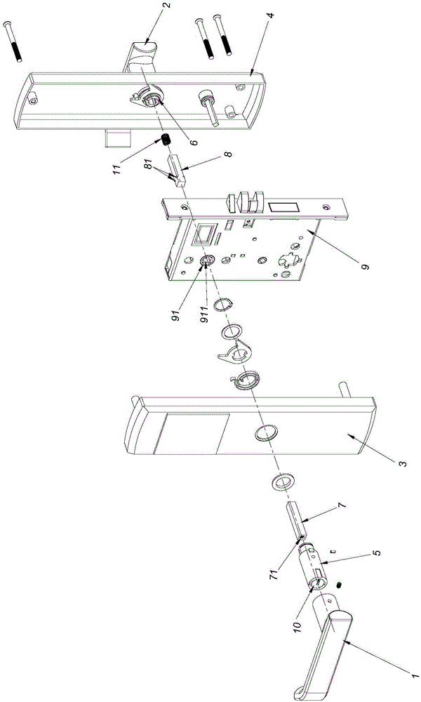
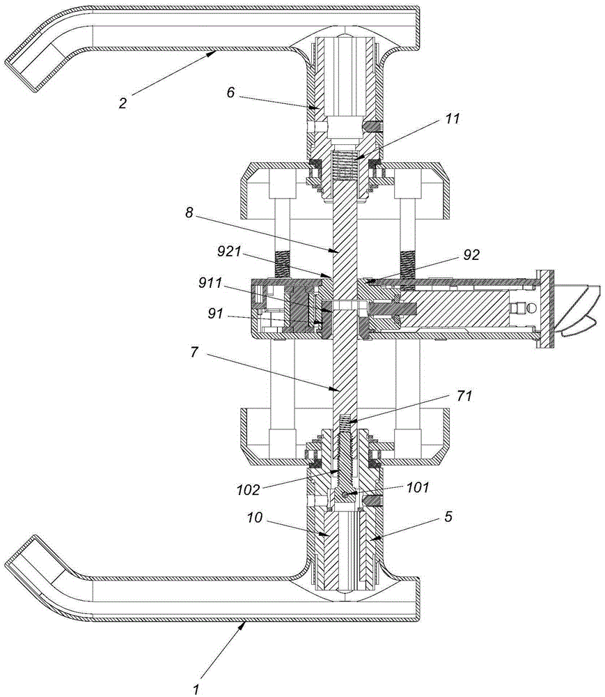
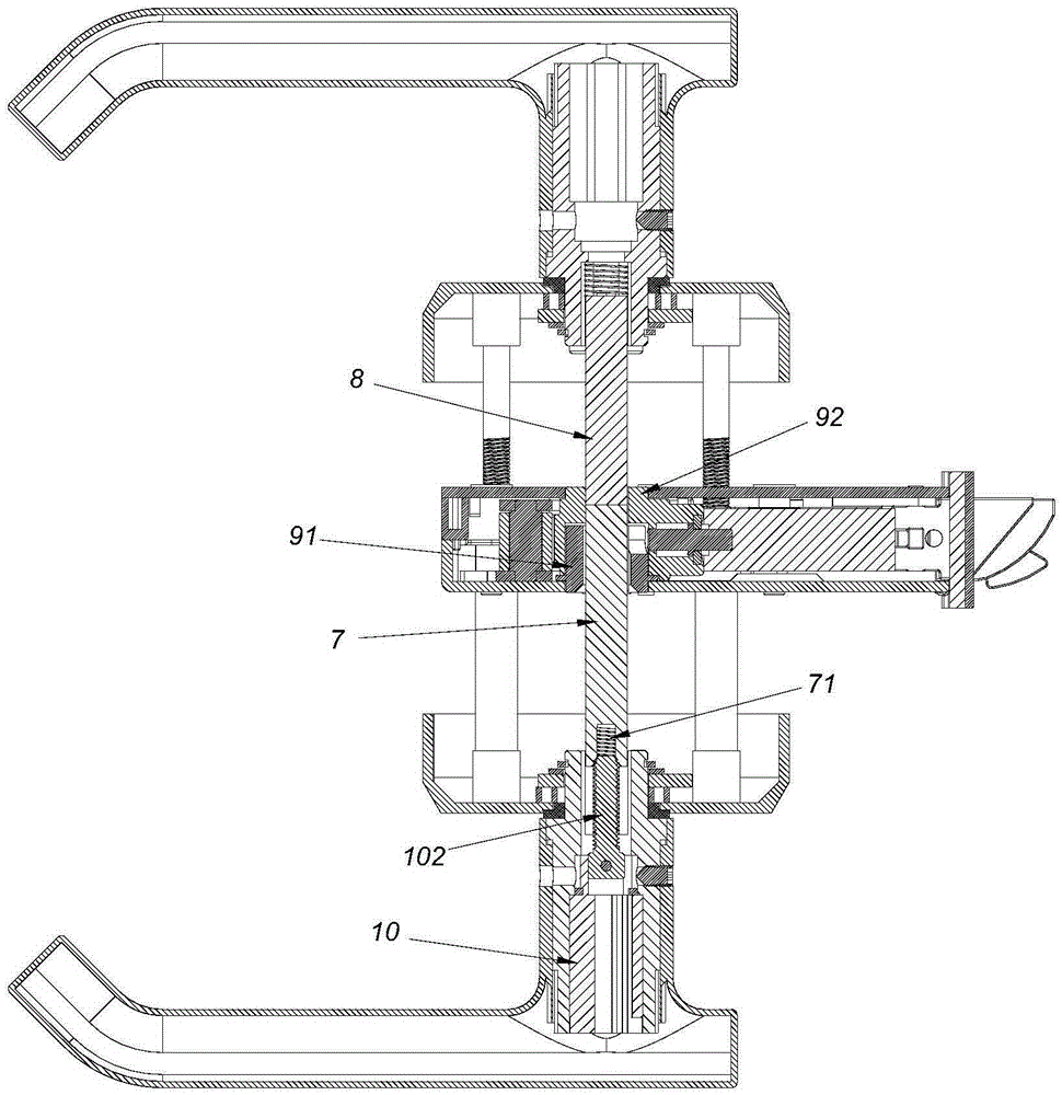
[0026] Such as figure 1 , figure 2 As shown, the lockset of this embodiment includes: an outer handle 1, an inner handle 2, an outer panel 3, an inner panel 4, a first connecting seat 5, a second connecting seat 6, a first transmission rod 7, a second transmission rod 8, Lock body 9 and lock core 10. The lock body 9 is provided with an outer rotating block 91 and an inner rotating block 92 . An outer rod hole 911 is formed on the outer rotating block 91 , and an inner rod hole 921 is formed on the inner rotating block 92 . The first transmission rod 7 and the second transmission rod 8 are commonly used square rod styles. One end of the first transmission rod 7 is located in the rod hole of the first connecting seat 5 , and the other end of the first transmission rod 7 is located in the outer rod hole 911 . One end of the second transmission rod 8 is located in the rod hole of the second connecting se...

Embodiment 2

[0031] This embodiment is about a cylinder locking device of the present invention.

[0032] Such as Figure 4 , Figure 5 , Image 6As shown, it includes: connecting seat 1', lock cylinder 2' and transmission rod 3'. The lock core 2' is in the connecting seat 1', and after inserting the correct key, the lock core 2' can rotate relative to the connecting seat 1'. One end of the transmission rod 3' is also in the connection seat 1', and the transmission rod 3' can not rotate relative to the connection seat 1', but can move linearly along the central axis of the transmission rod 3' relative to the connection seat 1'. On the end where the non-lock hole of the lock core 2' is located, an external threaded part 5' is connected by a latch 4', and the central axis of the external threaded part 5' is collinear with the axis of rotation of the lock core 2'; 'A threaded hole 6' is formed on the end close to the lock core 2', and the external screw 5' is screwed into the threaded hol...

Embodiment 3

[0035] This embodiment is about another cylinder locking device of the present invention.

[0036] The difference between this embodiment and embodiment 2 is: the production position / formation position of the external screw member 5' and the screw hole 6' in the embodiment 2 are exchanged.


PUM


Abstract

The invention provides a keyhole concealed lockset. The keyhole concealed lockset is free of the arrangement of a keyhole cover plate, and the appearance of the lockset is not influenced at all. The keyhole concealed lockset comprises a first connecting base, a second connecting base, a first driving rod, a second driving rod and a lock body. The lock body is provided with an outer turning block and an inner turning block. An outer rod hole is formed in the outer turning block. An inner rod hole is formed in the inner turning block. Specially, a lock cylinder is further installed in the first connecting base. Screw driving of the lock cylinder and the first driving rod is formed. The screw driving is that the turning of the lock cylinder is transferred into the linear movement of the first driving rod. The screw driving makes the length of the first driving rod extending out of the first connecting base at least be ensured that the end of the first driving rod in the outer rod hole can reach the interior of the inner rod hole. The keyhole concealed lockset has the advantages of being simple in structure, good in concealing effect of a keyhole, compact in structure and the like. The invention further provides a lock liner device to make the keyhole of an existing lockset be concealed deeply.

Description

technical field [0001] The present invention relates to a lockset with an outer handle and an inner handle, in particular to a lockset whose lock hole cannot be observed from the outside; the present invention also provides a lock cylinder, in particular to a cylinder lock device with a telescopic transmission rod . Background technique [0002] At present, electronic locks such as fingerprint door locks and RFID card locks, even if the related electronic devices are advanced, still need to be equipped with mechanical lock cylinders to open the door after the electronic device is damaged or the power is cut off. Because mechanical lock cylinders are not commonly used, these electronic locks will hide the keyhole of the mechanical lock cylinder during design. The conventional method is: 1) the lock hole is set on the door lock panel, and the lock hole is covered with a cover plate; 2) the electronic lock is designed to hide the fingerprint operation panel with a decorative c...

Claims


Application Information

Patent Timeline
IPC IPC(8): E05B3/00E05B63/14E05B15/00
Inventor 邓其柏林聪
Owner ZHAOQING KAIDA HARDWARE DECORATION CO LTD
Why Eureka
Try Eureka