Centrifugal fan blade and centrifugal fan

A technology of centrifugal fan blade and blade shape, which is applied in the direction of mechanical equipment, machine/engine, liquid fuel engine, etc. It can solve the problems that are not conducive to improving the sound quality, reducing the efficiency of the fan, and reducing the noise of the unit, so as to reduce the impact loss , Improve aerodynamic efficiency and reduce noise

Active Publication Date: 2016-01-27
GREE ELECTRIC APPLIANCES INC
View PDF9 Cites 6 Cited by
  • Summary
  • Abstract
  • Description
  • Claims
  • Application Information

AI Technical Summary

Problems solved by technology

[0002] In the prior art, the backward centrifugal fan blade of the patio machine has no obvious change in the phase angle along the circumferential direction from the front cover plate to the rear cover plate blade inlet edge, which is not conducive to reducing the noise of the unit, and is not conducive to improving the sound quality; the blade outlet edge and the front cover plate The smaller the included angle, the easier it is to create a stagnant area of ​​the airflow, which reduces the efficiency of the fan.

Method used


Image

  • Centrifugal fan blade and centrifugal fan
  • Centrifugal fan blade and centrifugal fan

Examples


Embodiment Construction

[0017] The present invention will be described in detail below with reference to the accompanying drawings and examples.

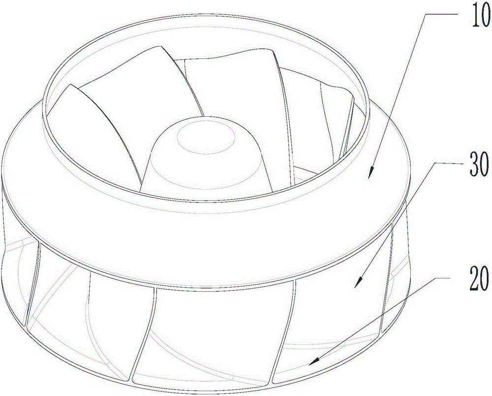
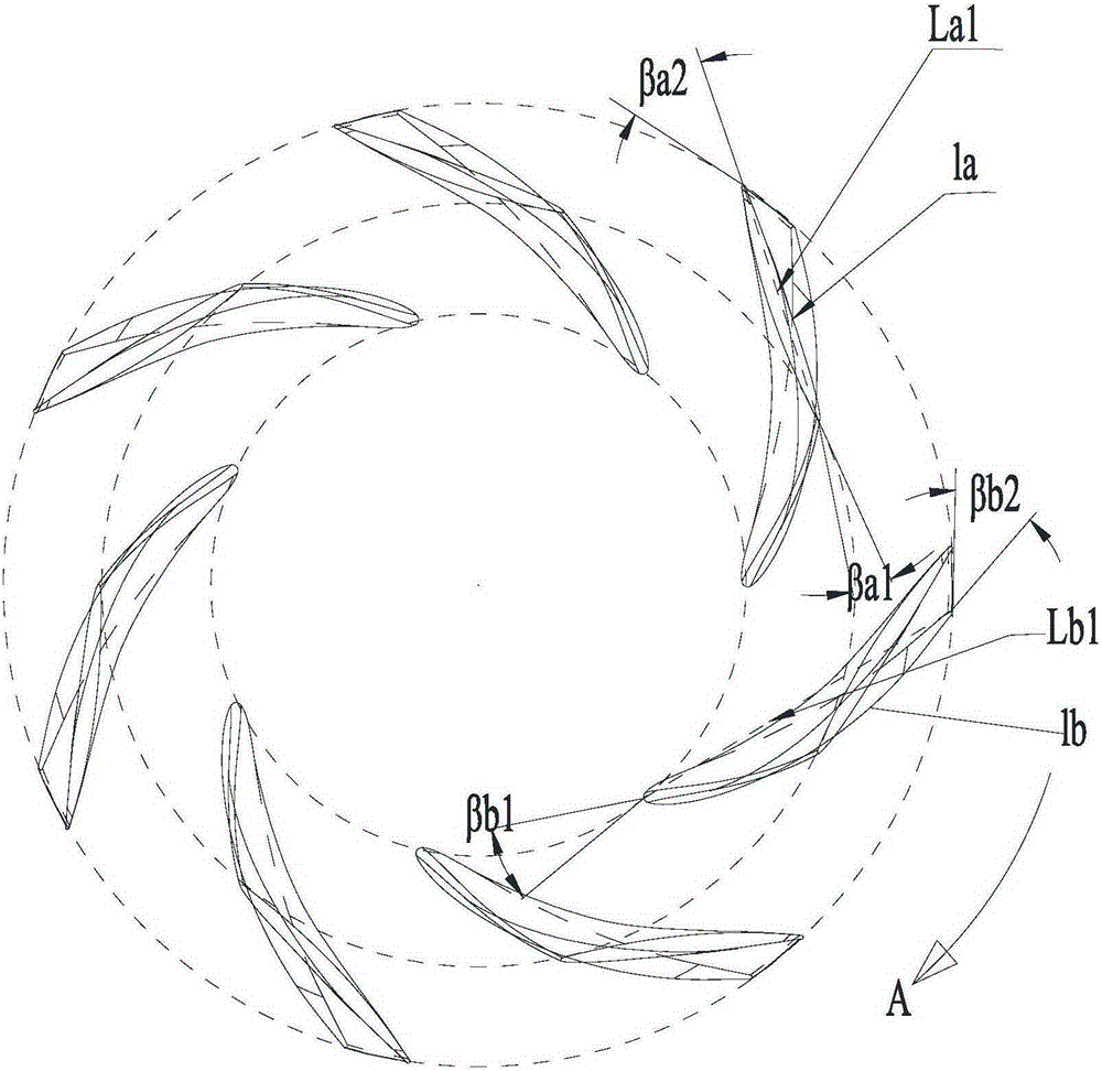
[0018] Such as figure 1 and figure 2 As shown, the centrifugal fan blade according to the present invention includes a front cover plate 10, a rear cover plate 20 and a plurality of blades 30 arranged between the front cover plate 10 and the rear cover plate 20, where the blades 30 and the front cover plate 10 are connected The inlet angle of the airfoil is βa1; the inlet angle of the airfoil at the connection between the blade 30 and the rear shroud 20 is βb1, where βa1<βb1. In the present invention, the airfoil inlet angle βa1 at the joint between the blade 30 and the front shroud 10 is smaller than the airfoil inlet angle βb1 at the joint between the blade 30 and the rear shroud 20, thereby reducing the impact loss of the airflow at the inlet and reducing noise , improve the aerodynamic efficiency of the fan blade.

[0019] Preferably, the airfoil i...


PUM


Abstract

The invention provides a centrifugal fan blade and a centrifugal fan. The centrifugal fan blade comprises a front cover plate (10), a rear cover plate (20) and a plurality of blades (30) arranged between the front cover plate (10) and the rear cover plate (20). Blade profile inlet angles at the joints of the blades (30) and the front cover plate (10) are betaa1, and blade profile inlet angles at the joints of the blades (30) and the rear cover plate (20) are betab1, wherein betaa1 is smaller than betab1. According to the centrifugal fan blade and the centrifugal fan, the blade profile inlet angles at the joints of the blades (30) and the front cover plate (10) are smaller than the blade profile inlet angles at the joints of the blades (30) and the rear cover plate (20), and therefore the impact of airflow at an inlet can be reduced, noise is lowered, and the pneumatic efficiency of the fan blade is improved.

Description

technical field [0001] The invention relates to the field of centrifugal fans, in particular to a centrifugal fan blade and a centrifugal fan. Background technique [0002] In the prior art, the backward centrifugal fan blade of the patio machine has no obvious change in the phase angle along the circumferential direction from the front cover plate to the rear cover plate blade inlet edge, which is not conducive to reducing the noise of the unit, and is not conducive to improving the sound quality; the blade outlet edge and the front cover plate The smaller the included angle, the easier it is to generate airflow stagnation area, which reduces the efficiency of the fan. Contents of the invention [0003] The invention aims to provide a centrifugal fan blade and a centrifugal fan capable of improving noise reduction. [0004] The invention provides a centrifugal fan blade, which includes a front cover, a rear cover and a plurality of blades arranged between the front cover...

Claims


Application Information

Patent Timeline
Patent Type & Authority Applications(China)
IPC IPC(8): F04D29/30F04D29/66
Inventor 苏起钦周伟峰余锐生
Owner GREE ELECTRIC APPLIANCES INC
Why Eureka
Try Eureka