Strengthening and application of power type vane pump

A power and power output technology, applied in the extended application field of this method, can solve the problems of small output pressure or flow rate, reduced application volume and range, low fluid and power exchange efficiency, etc., to expand the application range and improve energy exchange efficiency effect

Active Publication Date: 2016-01-27
何家密
View PDF7 Cites 4 Cited by
  • Summary
  • Abstract
  • Description
  • Claims
  • Application Information

AI Technical Summary

Problems solved by technology

[0002] At present, the dynamic vane pump has stable fluid output, basically no pulsation, and the rolling fit between the pump vane and the pump body is non-contact friction. It is widely used, but its output pressure or flow is small as a pump. The power exchange efficiency is low, which reduces its application volume and scope, so it is an important issue to increase the output pressure and efficiency of the pump, and to improve the exchange efficiency of the fluid and power of the power vane pump as a motor.

Method used


Image

  • Strengthening and application of power type vane pump
  • Strengthening and application of power type vane pump
  • Strengthening and application of power type vane pump

Examples


Embodiment Construction

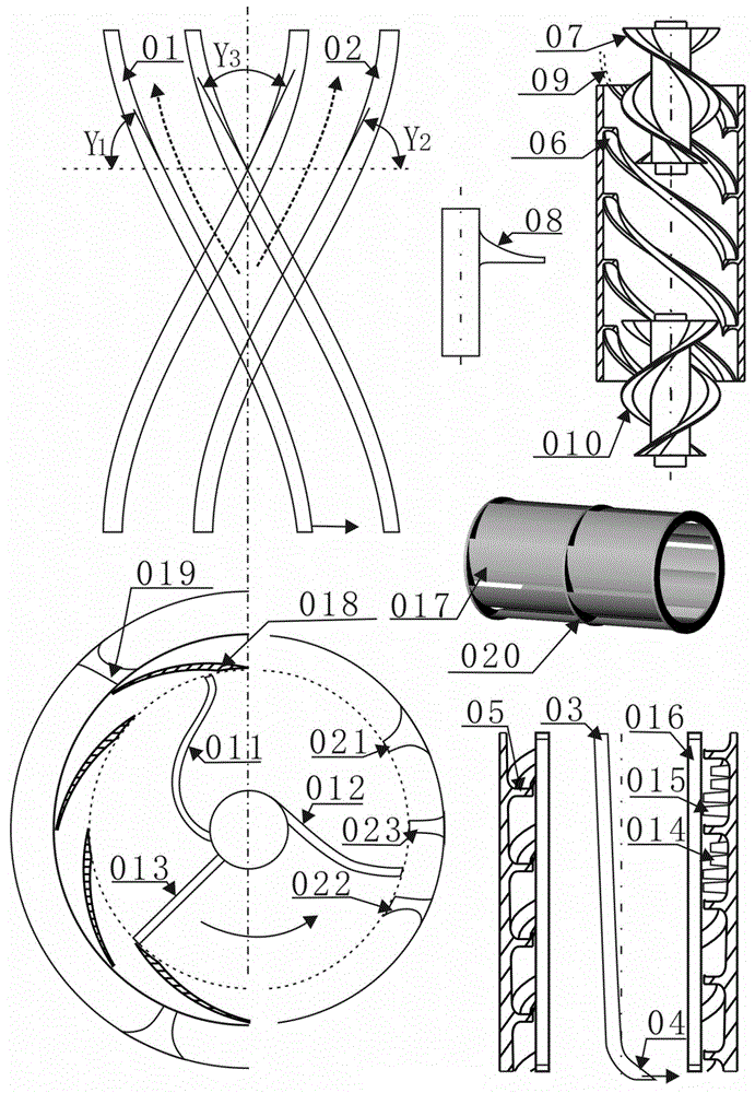
[0014] exist figure 1 Among them, the fins (7, 9, 11, 16, 17) of the pump supercharger are subjected to the rotational movement of the pump blades (10, 12, 14) so ​​that the fluid is sheared and extruded to flow to the fins of the supercharger One side, (2) is the action fluid surface of the sharp angle between the supercharger fin and the pump blade, and the mating surface of the pump blade (in the application of axial flow pump) or the tangent line of the sharp angle (in the application of centrifugal pump) (18) The included angle is R 2 , the smaller the angle is, the better it is for the supercharger fin to shear the fluid, and the more the conversion efficiency between the power of the pump blade and the fluid flow is increased; (8) is the matching surface of the supercharger fin and the sharp angle of the pump blade at the shortest distance, ( The sharp angle formed by 2 and 8) is the closest part between the turbocharger fin and the pump blade, (8) and the pump blade m...


PUM


Abstract

The invention discloses strengthening and application of a power type vane pump. A reasonable relation between fluid and power is obtained by means of the shape structure of parts of the pump and fluid features, and superchargers (017 and 423) with the small-angle R2 and small R1 and R2 fluid inlet included angle fins are added to the output end of pump vanes. Fins (06 and 410) are combined with the inner side of a pump shell to become flow channels to increase the output pressure or flow of fluid. Inner stators (52 and 510) of the spiral flow channels enable the fluid to impact rotors (51 and 511) with particle bars (512) on the inner surface of the pump shell in a centrifugal rotation manner for power output. The high-pressure fluid of pipelines (906 and 918) are used for impacting the small-radius part of a high-pressure fluid impacting pump blade (908) or large-radius parts of parts (911 and 916), backward flowing is conducted, and the rotation power output of rotors where the blades are located is obtained. A transmission device conducting transmission through the fluid force is formed by rotors with fins (52, 510, 416 and 419) and rotors with particle bars (51, 511, 415 and 418) on the inner side of the pump shell.

Description

technical field [0001] The invention relates to a power vane pump or motor that directly exchanges power with fluid energy, especially can increase the output pressure, flow rate, efficiency of the power pump or the rationality and efficiency of the motor absorbing fluid power, and the extended application of the method. Background technique [0002] At present, the dynamic vane pump has stable fluid output, basically no pulsation, and the rolling fit between the pump vane and the pump body is non-contact friction. It is widely used, but its output pressure or flow as a pump is small. The power exchange efficiency is low, which reduces its application volume and scope, so it is an important issue to increase the output pressure and efficiency of the pump, and to improve the exchange efficiency of the fluid and power of the power vane pump as a motor. Contents of the invention [0003] The purpose of the present invention to solve the technical problem is to improve the ene...

Claims


Application Information

Patent Timeline
Patent Type & Authority Applications(China)
IPC IPC(8): F04D29/44F04D29/54F04D29/42F04D29/52F04D29/18F04D29/22F04D29/24F04D29/26F04D29/30F04D29/32F04D29/38F01D1/04F01D25/24F01D5/02F03B3/04F03B3/12
CPCY02E10/20
Inventor 不公告发明人
Owner 何家密
Why Eureka
Try Eureka