
A Double-pipe Liquid Inerter with Variable Inertia Coefficient

A technology of inertia coefficient and dual pipelines, applied in the field of vehicle suspension system, can solve the problems of short service life, high production cost and low production efficiency of the mechanism, and achieve the effects of long service life, vibration reduction and stable operation of the mechanism

Inactive Publication Date: 2017-12-05
JIANGSU UNIV
View PDF1 Cites 3 Cited by
  • Summary
  • Abstract
  • Description
  • Claims
  • Application Information

AI Technical Summary

Problems solved by technology

[0006] Aiming at the deficiencies of the prior art, the present invention provides a double-pipeline liquid inerter with a variable inertial coefficient, which can effectively solve the problem of invariable inertial coefficient, complex structure, short mechanism life, and problems in processing and installation of existing inerter equipment. Difficulty, high production cost and low production efficiency

Method used


Image

  • A Double-pipe Liquid Inerter with Variable Inertia Coefficient
  • A Double-pipe Liquid Inerter with Variable Inertia Coefficient
  • A Double-pipe Liquid Inerter with Variable Inertia Coefficient

Examples


Embodiment 1

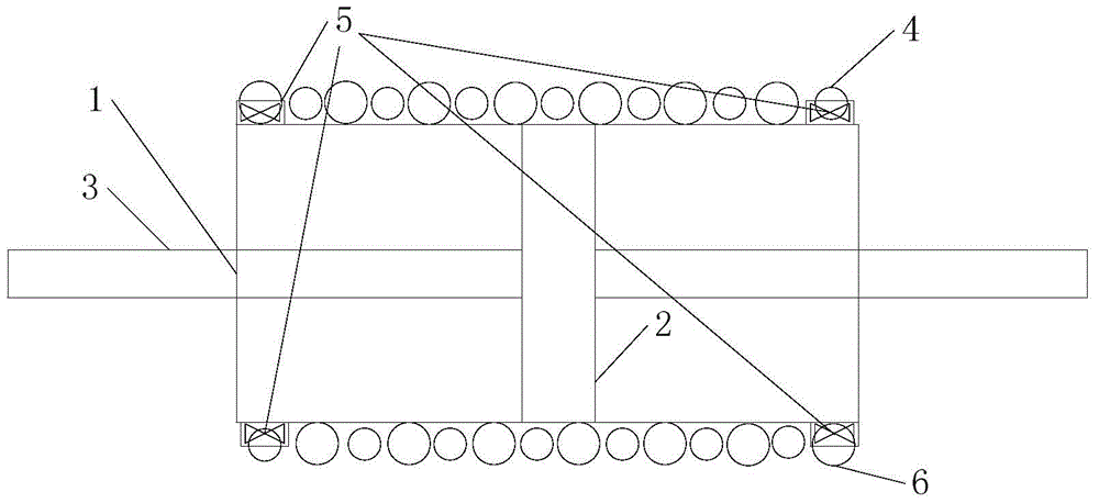
[0029] Such as figure 1 As shown, the first metal helical pipeline 4 and the second metal helical pipeline 6 have different radii and the same helical radius, and are arranged on the same cylindrical surface.

[0030] Let: r 1 is the radius of piston 2, r 2 is the inner radius of hydraulic cylinder 1, r 31 is the inner radius of the first metal spiral pipe 4, r 32 is the inner radius of the second metal spiral pipe 6, r 4 is the radius of the helix, h is the pitch of the helix, n is the number of turns of the helix, L is the inner length of the hydraulic cylinder 1, and ρ is the density of the liquid.

[0031] Like springs, dampers, capacitors, resistors, and inductances, inerters are also ideal components. Therefore, when abstracting an actual device into an inerter, some secondary factors must be ignored, such as small sliding friction. Like the ideal hydraulic damper equipment, the quality of the piston 2, the piston rod 3, the hydraulic cylinder 1 and the oil should b...

Embodiment 2

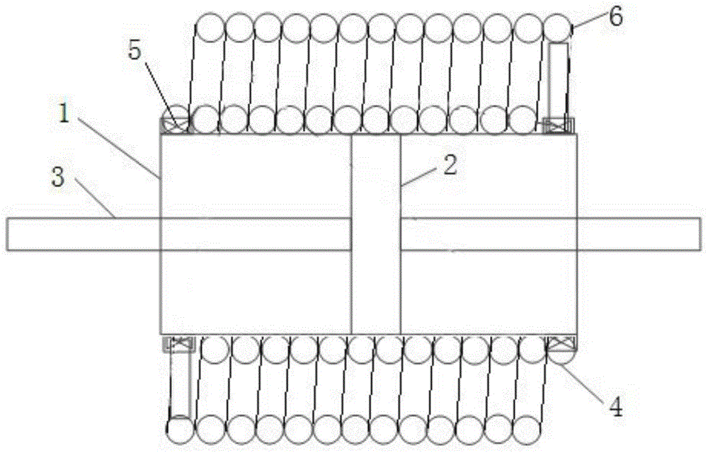
[0067] Such as figure 2 As shown, the first metal helical pipeline 4 and the second metal helical pipeline 6 have the same radius and different helical radii, and are arranged on two concentric cylindrical surfaces.

[0068] Let: r 1 is the radius of piston 2, r 2 is the inner radius of the hydraulic cylinder 1, the radius of the first metal helical pipeline 4 and the second metal helical pipeline 6 is r 3 , r 41 is the spiral radius of the first metal spiral pipeline 4, r 42 is the helical radius of the second metal helical pipeline 6, h is the pitch of the helix, n is the number of turns of the helix, L is the inner length of the hydraulic cylinder 1, and ρ is the density of the liquid.

[0069] Same as in Example 1, some minor factors are ignored and idealized.

[0070] The cross-sectional area of ​​the hydraulic cylinder A 1 = π(r 2 2 -r 1 2 ), the cross-sectional area A of the first metal helical pipeline 4 and the second metal helical pipeline 6 2 '=πr 3 2 ...


PUM


Abstract

The invention provides a double-pipe liquid inerter with variable inertia coefficient, which includes a hydraulic cylinder, a piston, a piston rod, two metal spiral pipelines, an on-off control valve and other connecting parts. The piston is placed in the hydraulic cylinder, which divides the hydraulic cylinder into two chambers, the piston rod is connected to the piston, and the two ends of the two metal spiral tubes are respectively connected to the two chambers of the hydraulic cylinder. switch control valve. The present invention changes the parameters of the inerter by changing the quality of the oil in the liquid inerter, can control the on-off of the pipeline by controlling the switch of the valve, and adjust the circulation mode of the oil to realize the characteristics of "large", "medium" and "small". A liquid inerter device with three-stage adjustable inertia coefficient. Compared with the prior art, the present invention has the advantages of adjustable inertia coefficient, stable mechanism operation, simple structure, fewer components, easy processing and assembly, lower cost, high production efficiency and long service life.

Description

technical field [0001] The invention belongs to the field of vehicle suspension systems, in particular to a double-pipeline inerter device with variable inertia coefficients for the automobile suspension system using inerters. Background technique [0002] SIMTH, a scholar at the University of Cambridge, proposed the idea of ​​an inerter in 2002, and after designing the rack and pinion inerter and the ball screw inerter, the strict correspondence between the mechanical and electronic networks was realized, and the development of the mechanical network was promoted. . After the strict correspondence between mechanical and electronic networks, a large number of electronic network theories and research methods can be applied to mechanical systems, including automobile suspension systems, vehicle steering systems, train suspension systems, building vibration isolation systems, helicopter vibration isolation systems, and dynamic vibration absorption systems. Devices, etc., and d...

Claims


Application Information

Patent Timeline
Patent Type & Authority Patents(China)
IPC IPC(8): F16F9/20F16F9/34
CPCF16F7/1034
Inventor 陈龙刘昌宁张孝良沈钰杰杨军黄振兴张华新
Owner JIANGSU UNIV
Learn More