Gear rack type inertial container with variable inertial coefficient

A technology of inertia coefficient and rack and pinion is applied in the field of inertial container devices, which can solve the problems of large self-weight and instantaneous large impedance, and achieve the effect of reducing self-weight and having a simple and easy structure.

Inactive Publication Date: 2012-06-20
JIANGSU UNIV
View PDF4 Cites 31 Cited by
  • Summary
  • Abstract
  • Description
  • Claims
  • Application Information

AI Technical Summary

Problems solved by technology

[0005] In the application process, due to the uniform flywheel used in the rack and pinion type inerter, its own weight is relatively large, and its inertia coefficient cannot be changed once it is designed, especially under the instantaneous action of large loads, due to the effect of internal mechanical inertia, It is easy to generate instantaneous large impedance and overload

Method used


Image

  • Gear rack type inertial container with variable inertial coefficient
  • Gear rack type inertial container with variable inertial coefficient
  • Gear rack type inertial container with variable inertial coefficient

Examples


Embodiment Construction

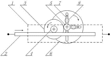
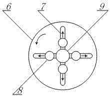
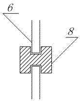
[0019] exist figure 1 Among them, the rack 2 is placed in the guide rail of the box 1 and can move in translation. The rack 2 and the box 1 are two opposite free ends of the inerter. The rack 2 meshes with the pinion shaft B4, the pinion shaft B4 and the bull gear 3 are coaxially connected and fixed on the box body 1, the pinion shaft A5 meshes with the bull gear 3, and the flywheel 6 and the pinion shaft A5 are coaxially connected It is fixed on the box body 1, and four guide grooves 7 are opened on the flywheel 6. The length of the guide groove 7 is less than the radius of the flywheel 6. The mass block 8 is placed in the guide groove 7 and is nested so that the mass block 8 can move along the The guide groove 7 slides radially.

[0020] exist figure 2 Among them, a magnetic ferrule is placed at the axis of the flywheel 6 to ensure that the mass 8 can be adsorbed near the axis of the flywheel when it is still.

[0021] Let the gear radius of the pinion shaft B4 be r 1 ...


PUM


Abstract

A gear rack type inertial container with a variable inertial coefficient is characterized in that a guide groove is arranged on a flywheel of the inertial container, a mass block capable of freely and radially moving in the guide groove is nested in the guide groove, and a magnetic sleeve ring is arranged at the axis of the flywheel and can suck the mass block to a position close to the axis of the flywheel when being static. When a pair of external forces oppositely acts at two endpoints of the inertial container, a rack indirectly drives the flywheel fixed onto a box to rotate, and centrifugal force enables the mass block to radially move, so that the inertial coefficient changes along with the movement state, impact generated in instantaneous action of high load is relieved, the dead weight of the inertial container can be reduced, and the inertial container is simple and practicable in structure.

Description

technical field [0001] The invention relates to an inerter device, in particular to a rack and pinion type inerter device with variable inertia coefficient. Background technique [0002] Chinese patent 200810123830.8 discloses a rack-and-pinion inerter, also called rack-and-pinion inertial mass accumulator or rack-and-pinion inertial accumulator, just like the spring and damper in the mechanical system, this device does not need The inertial coordinate system is the frame of reference and is a true two-point element. In the new electromechanical simulation theory, by using this device to replace the traditional mass components, the simulated components in the mechanical and circuit systems are strictly equal, thus solving the problem in the application of electromechanical simulation theory. The device can be widely used in the field of vibration isolation technology, such as vehicle suspension, train suspension, building anti-shock and absorbing dynamic mechanical vibratio...

Claims


Application Information

Patent Timeline
Patent Type & Authority Applications(China)
IPC IPC(8): F16F15/31F16H33/00
Inventor 陈龙杨晓峰张孝良汪若尘
Owner JIANGSU UNIV
Why Eureka
Try Eureka