Lapped thermal shrinkage round pipe

A heat-shrinkable, round tube technology, applied in the direction of pipes/pipe joints/fittings, pipes, rigid pipes, etc., can solve the problems of large thickness of the lap joint and inconvenient sewing operation of the lap joint, and achieve the effect of improving stability

Inactive Publication Date: 2016-01-27
成都长江热缩材料有限公司
View PDF8 Cites 8 Cited by
  • Summary
  • Abstract
  • Description
  • Claims
  • Application Information

AI Technical Summary

Problems solved by technology

[0004] The technical problem to be solved by the present invention is to provide overlapping heat-shrinkable round tubes to overcome the problems of inconvenient sewing operation and large thickness of the lapped parts of existing heat-shrinkable round tubes

Method used


Image

  • Lapped thermal shrinkage round pipe
  • Lapped thermal shrinkage round pipe
  • Lapped thermal shrinkage round pipe

Examples


Embodiment 1

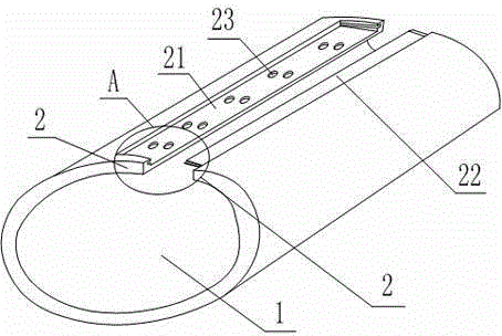
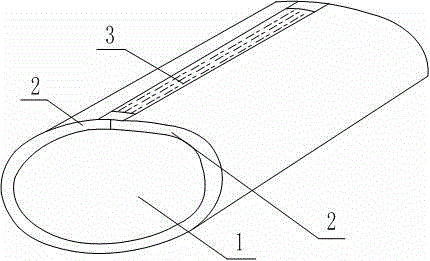
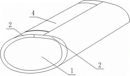
[0025] Such as Figure 1 to Figure 4 As shown, the overlapping heat-shrinkable circular tube is rolled into a tubular shape from a sheet-shaped heat-shrinkable material 1, and the tubular shape includes two overlapping sections 2, and a U-shaped groove 21 is provided on the outside of one of the overlapping sections 2, and the U-shaped The two sidewalls of the groove 21 are symmetrically provided with two draw-in grooves 24, and the outside of the other lap section 2 is provided with a boss 22 cooperating with the U-shaped groove 21, and the two ends of the boss 22 are provided with a draw-in groove 24. Convex 25, the outer side of described lap section 2 is provided with suture 3 that sutures U-shaped groove 21 and boss 22 together, and the outside of suture 3 is provided with heat-sealing layer 4; Said suture 3 selects nylon for use, can also Is nylon, polyester or aramid.

[0026] The working process of the present invention: before the lap section 2 is sutured, the boss 2...

Embodiment 2

[0028] Such as Figure 1 to Figure 4 As shown, this embodiment is based on Embodiment 1, the bottom of the U-shaped groove 21 is provided with a groove 23, and the inner side of the boss 22 is provided with a protrusion that cooperates with the groove 23; The height of the side wall is 1 / 2 of the sheet-like heat-shrinkable material 1, and there are three sutures 3; the diameter of the suture 3 is 0.4mm; the groove 23 is a hemispherical structure, which can also be Ellipsoid structure.


PUM


Abstract

The invention relates to a lapped thermal shrinkage round pipe; a pipe-shaped thermal shrinkage material is coiled to a pipe shape; the pipe shape comprises two lapped sections; a U-shaped groove is formed in the outer side of one lapped section; two clamping grooves are symmetrically formed in the two side walls of the U-shaped groove; a boss fitting the U-shaped groove is arranged at the outer side of the other lapped section; convex edges of the clamping grooves are arranged at the two ends of the boss; stitching lines for stitching the U-shaped groove and the boss are arranged at the outer sides of the lapped sections; and thermal sealing layers are arranged at the outer sides of the stitching lines. As the U-shaped groove and the boss are respectively arranged at the outer sides of the two lapped sections, the convex edges are inserted in the corresponding clamping grooves to realize the fixation of the U-shaped groove and the boss, and the two lapped sections are fixed to prevent the deviation problem thereof in stitching.

Description

technical field [0001] The invention relates to the technical field of heat-shrinkable tubes, in particular to lap-joint heat-shrinkable circular tubes. Background technique [0002] At present, the oil and gas industry uses a large number of steel pipes for long-distance transportation. After the steel pipes are connected, heat-shrinkable sheets are used to fill the joints. The material used for the joints is generally a fixed-piece heat-shrinkable tape, which is troublesome to operate and the quality of the joints is unstable. For this reason, the fixed piece and the heat shrinkable tape of the fixed piece type heat shrinkable sheet are usually prefabricated in the factory and joined into a round tube type heat shrinkable sleeve to make the user convenient to operate and stable in quality when using the heat shrinkable tape to fill the joint. However, the current joining method of the round tube heat-shrinkable sleeve adopts the direct heating and pressing method, which is...

Claims


Application Information

Patent Timeline
Patent Type & Authority Applications(China)
IPC IPC(8): F16L9/17
CPCF16L9/17
Inventor 穆宏荣
Owner 成都长江热缩材料有限公司
Why Eureka
Try Eureka