Natural gas drain valve capable of draining water continuously

A natural gas and steam trap technology, applied in steam traps, mechanical equipment, etc., can solve problems such as poor adaptability to pressure changes, inability to ensure continuous and rapid discharge of separated liquid, and complex structure of steam traps. The effect of avoiding air leakage

Inactive Publication Date: 2016-01-27
NANJING RECLAIMER ENVIRONMENTAL TEKNIK
View PDF11 Cites 2 Cited by
  • Summary
  • Abstract
  • Description
  • Claims
  • Application Information

AI Technical Summary

Problems solved by technology

[0009] However, the structure of the steam trap in the above patent is relatively complicated, and it cannot guarantee the continuous and rapid discharge of the separation liquid, and the adaptability to pressure changes is poor.

Method used


Image

  • Natural gas drain valve capable of draining water continuously

Examples


Embodiment 1

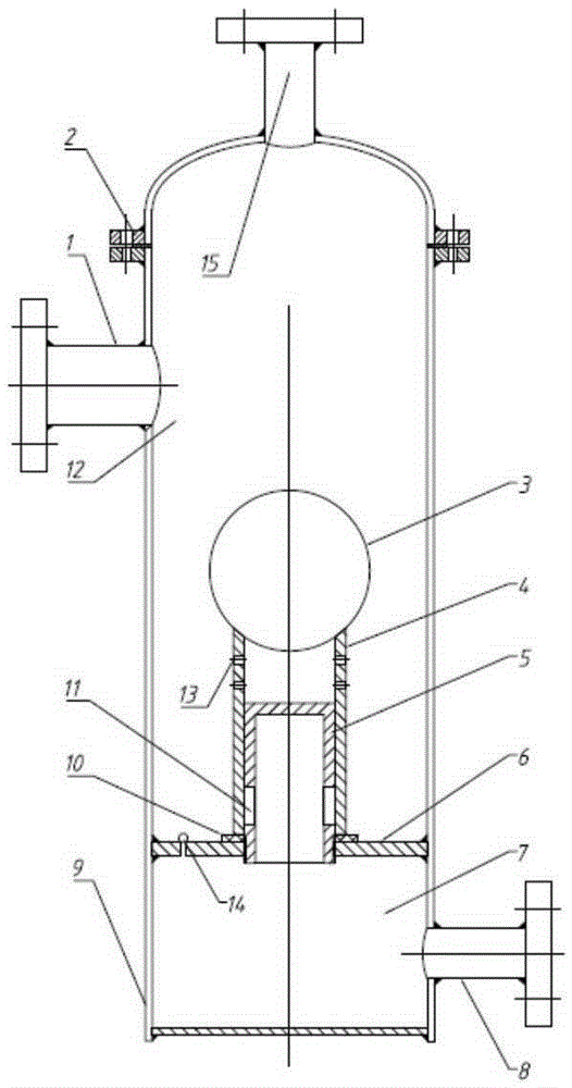
[0039] Such as figure 1 Shown is a structural schematic diagram of a continuous drainage natural gas trap of the present invention.

[0040] Below by specific embodiment, in conjunction with its accompanying drawing, this scheme is elaborated:

[0041] A natural gas trap for continuous drainage, the natural gas trap includes a large hydrophobic functional module A and a small hydrophobic functional module B, the upper end of the valve core A is connected to the hydrophobic functional module A, and the valve body 9 is provided with a gas Liquid mixture inlet 1 and separating liquid outlet 8, the valve body 9 is fixedly connected with a valve seat 6, and the valve seat 6 divides the inner cavity of the valve body 9 into an upper cavity 12 and a lower cavity 7, and the valve seat 6 A guide rail 5 is fixed on it, and the valve core A is installed in the cavity of the valve body 9 through the guide rail 5. The guide rail 5 adopts a hollow structure, and the gas-liquid mixture inle...


PUM


Abstract

The invention relates to a natural gas drain valve capable of draining water continuously. The natural gas drain valve is composed of a valve body and double valve elements. The large valve element is mounted in a cavity of the valve body through a guide rail. When the large valve element floats, separated liquid is drained from a separated liquid outlet through drain holes of the guide rail. A small drain function module is in a normally open state when a large drain function module works, and the small drain function module can remove accumulated water generated when the drain valve is out of operation. The drain quantity of the drain valve is adjusted automatically, and continuous draining can be achieved, so that the production safety of a gas field and stable operation of equipment are guaranteed.

Description

technical field [0001] The invention relates to a continuous drainage natural gas trap, which belongs to the technical field of gas field exploitation equipment. Background technique [0002] In the gas field production process, the automatic discharge of the separated liquid in the natural gas gas-liquid separator is an important part of the gas field production process. [0003] Regarding the design of natural gas traps, there are many mature structures: [0004] Patent CN203615046U discloses a natural gas trap, which changes the original design of the flow channel into an "L"-shaped flow channel composed of flow channel A and flow channel B, which relieves the leakage during the drainage process. It reduces the erosion of the seal by the medium and prolongs the overall service life of the trap. [0005] Patent CN202252808U provides a high-pressure natural gas trap, which is mainly composed of a trap body, a liquid inlet pipe installed on the trap body, a gas return pipe...

Claims


Application Information

Patent Timeline
Patent Type & Authority Applications(China)
IPC IPC(8): F16T1/22
Inventor 王海波彭启勇吴明
Owner NANJING RECLAIMER ENVIRONMENTAL TEKNIK
Why Eureka
Try Eureka